


The value of industrial switches in highway traffic scenarios is to connect scattered cameras, toll terminals, and monitoring devices back to the business platform. Selection cannot be derived from “the traffic market is large” to “must buy a Layer 3 Gigabit ring network.” Instead, you should first list the sites, business paths, fiber resources, and allowed interruption after a fault. This article keeps the original traffic application direction and focuses on explaining roadside access and fiber aggregation; for passenger information and ticket inspection/checking zones inside rail stations, see separately Rail Transit Networking Article .
1. How Roadside Data Reaches the Center
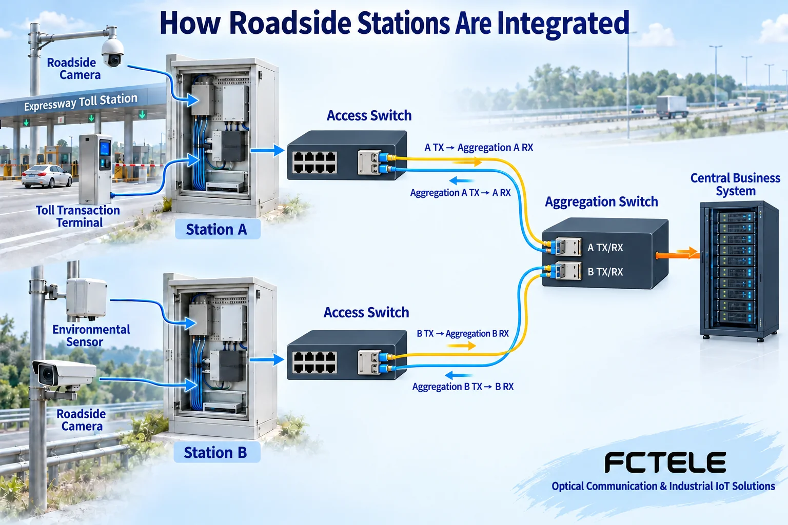
Take a hypothetical road section as an example: cameras generate video, toll terminals generate transaction records, and environmental sensors generate measurement data. Terminals first form data according to their own protocols, then send frames out from Ethernet ports. The access switch forwards according to addresses and configuration, and the optical port converts the corresponding electrical signal into an optical signal suitable for fiber transmission; the receiver at the other end restores the electrical signal and hands it to the subsequent network. Video decoding, toll processing, and alarm judgment are still completed by the application system.
Different sites can be connected to aggregation equipment through independent fibers, or connected according to an already designed link organization method. Star, tree, or ring topologies are not naturally suitable for all roads. If a ring connection does not have a matching anti-loop mechanism, it may instead cause data to loop; forming a ring network also does not mean that power supply, civil engineering conduits, and central equipment already have independent backup. Planning should draw every physical path, not just two lines in different colors.
2. Even If the Fiber Is Long Enough, Check Transmit and Receive Conditions
SFP is one form of pluggable transceiver module; the slot name itself cannot determine the communication distance. Both ends must check rate, interface, fiber type, wavelength matching, and device compatibility. In a dual-fiber link, the local transmit connects to the remote receive, and the two directions are checked separately; a bidirectional single-fiber module requires complementary transmit and receive wavelengths, and two modules with the same name cannot be arbitrarily paired as a pair.
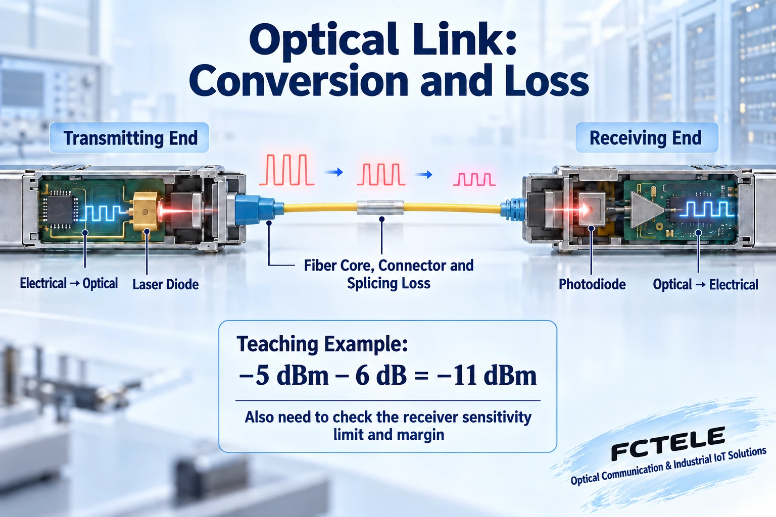
The optical signal will suffer loss after passing through the fiber core, connectors, and splice points. If the received light is too weak, reliable decision-making may be impossible; if it is too strong, it may also exceed the receiver’s allowed range. Optical power is commonly expressed in dBm, which has a reference base; path loss is expressed in dB, which is a quantity of power ratio. The two units cannot be mixed up, and a lit network port light cannot replace optical link acceptance.
For example, only to illustrate the calculation, assume the minimum output at the transmitter is −5 dBm and the path loss is 6 dB; the estimated received value is −11 dBm. It still needs to be compared with the sensitivity, overload limit, and required engineering margin of the selected receiver. This example is not a Feichang Technology module parameter, nor does it prove that a certain number of kilometers will definitely work. Line loss, dispersion, module temperature, and specific specification limits should still be checked against actual data and tests.
3. Business Zoning Cannot Replace Capacity Calculation
Toll, video, and management services can be divided into different VLANs according to design, thereby limiting the Layer 2 forwarding scope; cross-subnet access requires devices with routing capability and authorization rules. Not every roadside access point needs to run Layer 3 routing. If you only need to extend one service network to the center, adding routing functionality may not bring actual benefits, but instead increases addressing and maintenance configuration.
When multiple video streams are uploaded at the same time, the uplink bears the aggregated traffic. In addition to the average bitrate, you should also check bursts, playback, remote download, and management traffic. When the egress is busy, frames enter the buffer and queue; if the buffer is exhausted, they may be dropped. Priority can change the service order but does not increase link capacity; dividing VLANs also does not automatically reserve bandwidth for each service. After upgrading the optical port, you also need to check whether the central port, module, and server can bear it together.
4. Apply Product Capabilities to Clear Problems
Feichang Technology’s Managed Industrial Rail-Mount 10G 4-Fiber 8-Gigabit-Ethernet Layer 3 Switch Data lists 4 optical ports that can be selected according to supported specifications, 8 adaptive electrical ports, and management functions such as VLAN, Layer 3 routing, port statistics, logs, and SFP module information. The need for scattered electrical port access and higher-speed optical uplink can be checked against this for model verification; a detail page should not be generalized into proof that all traffic projects comply.
The dual power supplies in the data help organize power backup, but if both paths come from the same upstream power source, there is still a common failure risk. PoE is the ability to supply power to terminals through Ethernet cables; whether it is optional, the per-port limit, and the total budget must be confirmed separately. You cannot assume that a camera can be powered just because the device has an RJ45 interface. Cabinet water ingress, condensation, grounding, and surge paths also require engineering treatment; fiber being non-conductive cannot be understood as meaning the entire site is unaffected by lightning.
5. Fault Location Should Leave Evidence Segment by Segment
First confirm site power and terminal operation, then check electrical port negotiation, error counters, and optical port status, and finally verify the data received by the business system. If only one camera is abnormal, first compare it with other terminals at the same site; if all terminals under the same uplink are abnormal, then check the shared link and aggregation egress. Logs and counters should record time and port to avoid treating historical errors as current faults.
Optical port inspection uses a suitable power meter and cleaning method; do not look directly at the fiber end and do not arbitrarily replace modules of different specifications. Cable unplugging, power-off, and switching tests should only be performed in an isolated environment or an approved window, not risk-tested on a running toll or traffic control link. Final acceptance should save both communication results and application results such as video continuity and transaction record integrity; port reachability does not mean the service has been completed correctly.
Data note: The form, wavelength, and transmit/receive power limits of the transceiver module refer to Cisco SFP Installation and Specification Notes , and its parameters are not Feichang Technology specifications. Products are verified according to the above official website details. The two figures are general principle illustrations, not actual measurements or product photos.
Translated from the Chinese technical article. Source first published: 2021-07-27. Source last revised: 2026-10-13T11:20:43+08:00. Read the Chinese source
