


A multi-service fiber optic transmission device sends telephone, serial data, Ethernet and other services over optical fiber, but not all plugs will automatically interoperate just by being connected. During commissioning, first confirm that the equipment and service cards at both ends match, then connect power and the optical path, check interfaces, channels and parameters one by one, and finally accept the system using real services. The following explains this in the actual construction sequence.
1. First understand: sharing one fiber does not mean mixing into one service
You can think of the fiber optic transmission devices at both ends as two relay stations. The interface circuits at the local end first receive their respective electrical signals and complete encoding or interface adaptation according to the equipment design; the multiplexing part arranges different services into the optical transmission channel. After the remote end receives a valid signal, it separates them again, sending telephone back to the telephone port, serial data back to the corresponding serial port, and network data to the Ethernet port. Services in the reverse direction also need corresponding receive and transmit paths.
Multiplexing can reduce fiber usage, but it does not automatically eliminate interface differences. RS485 is an electrical interface, while Modbus is a message protocol; transparent serial transmission does not equal automatic protocol conversion. Analog telephone, IP telephone and E1 are also not the same type of interface. Without the corresponding service card or conversion capability, the function cannot be completed by simply changing a cable. Even if optical ports from different manufacturers have the same wavelength, that does not mean their proprietary multiplexing formats are compatible.
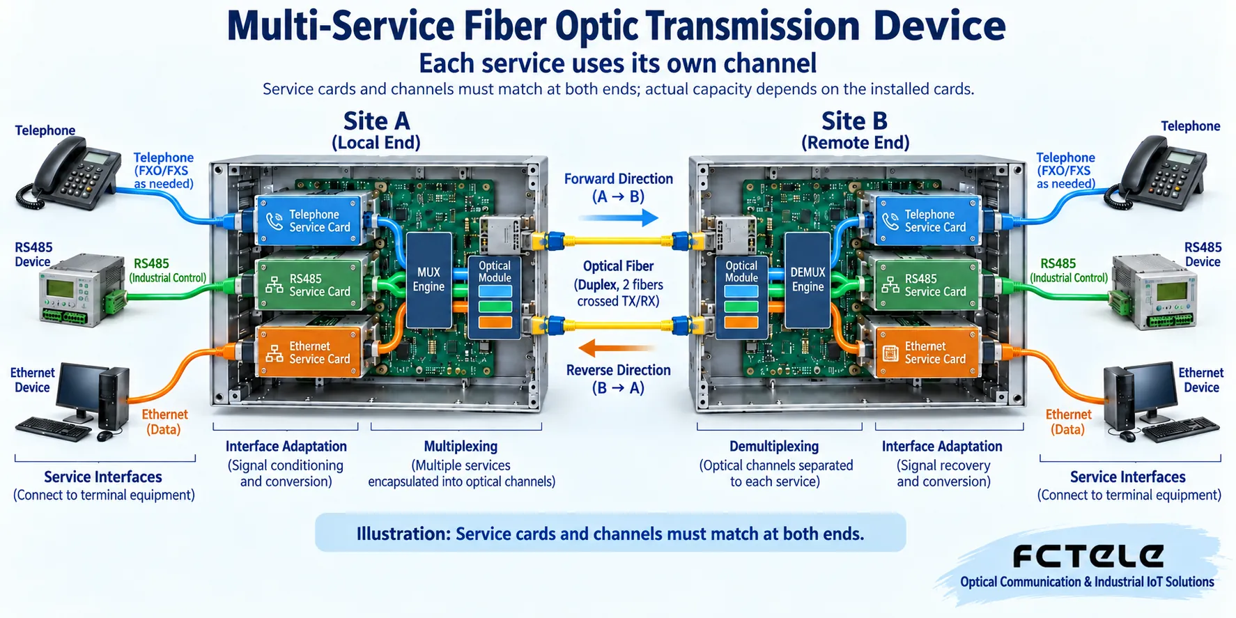
2. Turn the service list into a port table for both ends
Before construction, clearly write down the source, destination, interface type and direction of each service. For example, which pair of Ethernet ports the switch’s network port connects to; which pair of serial ports the instrument’s RS485 connects to; and through which pair of telephone ports the analog subscriber line of the telephone exchange is sent to the remote telephone. Record the equipment model, card slot number, port number and cable labels, and the two ends must correspond one to one.
Fixed-configuration equipment is used according to the factory port table; modular equipment also requires checking the card type, slot position and allowed combinations. You cannot assume that any card can be inserted just because you see an empty slot, and you cannot multiply the maximum capacity of a single card by the number of slots and treat that as something the whole chassis necessarily supports. The modular telephone fiber optic transmission device product page of Feichang Technology lists different service card combinations; procurement and construction should be based on the actual ordered configuration and the documentation supplied with the equipment.
Video services especially require confirming the format. BNC is only the connector shape and cannot prove that both ends are the same video signal. Analog video and SDI cannot be directly mixed just because the interfaces look the same; a network camera outputs Ethernet data, not an analog video input. Only when the equipment clearly supports the corresponding video service should the camera and receiving equipment be connected according to the input and output directions.
3. Connect power and optical fiber: first establish a reliable transmission foundation
Check the nameplate voltage, AC or DC type, polarity, protective grounding and installation heat dissipation. Power wiring must be completed by qualified personnel, and service ports must not be used to test power supply. The rack should be fixed, cables should have reasonable bending space, and connectors should be protected from pulling. Dual power supplies do not necessarily mean two truly independent paths; whether they come from the same upstream power source should also be recorded.
Before connecting optical fiber, check single-mode or multimode, single-fiber or dual-fiber, connector and module pairing information. A dual-fiber link should have the local transmit corresponding to the remote receive; for a single-fiber bidirectional link, select complementary transmit and receive wavelengths according to the module manual. Clean the connection end faces and keep them dust-proof, and never look directly at the optical port or fiber end face with your eyes. When using a long-distance module over a short distance, also check the receive overload range; do not only consider whether the optical power is strong enough.
Optical port has light, optical link synchronization and normal service are three different levels. First check the optical path status at both ends, then check whether the received power is within the window allowed by the specific module. When measurement is needed, use a suitable optical power meter and maintenance procedure, and do not treat one general dBm value as the pass line for all equipment.
4. Wire and set up each service separately
For telephone ports, first confirm the FXS and FXO roles. In common analog line extension, the side connected to the exchange’s analog subscriber line uses the corresponding FXO port, and the side connected to an ordinary analog telephone uses the corresponding FXS port; the specific arrangement should still be based on the equipment application diagram. Two power-supplying ringing interfaces must not be connected to each other at will. Testing should include incoming calls, outgoing calls, ringing, on-hook and off-hook, and two-way voice, not just hearing a dial tone.
For serial ports, first check RS232, RS422 or RS485, then check the pins, transmit and receive directions, two-wire or four-wire mode and reference ground requirements. The A/B labeling of RS485 may differ among manufacturers, so check the terminal definition and do not guess positive and negative only from the letters. The service terminal’s rate, data bits, parity and stop bits should be consistent with the link capability; terminating resistors and bias should be determined according to the bus structure. Transparent equipment still requires the service end to correctly set the device address and message protocol.
For Ethernet ports, check the negotiated rate, network cable, link status, and the VLAN and network configuration of the related switch. Seeing the LINK light does not mean a computer can definitely access the remote application; the service transmission port and the management port may also be separate, and assigning an IP to the management port does not mean assigning addresses to all services. If the equipment is transparent transmission, it should not be configured as a router without authorization.
For E1 services, check impedance, interface wire sequence, framing mode, time slot arrangement and clock source. A physical interface being connected does not mean the service time slots are consistent; a clock mismatch may appear as intermittent errors. First determine according to the design who provides the clock, then test the corresponding channel, and avoid randomly switching multiple clock options on site.
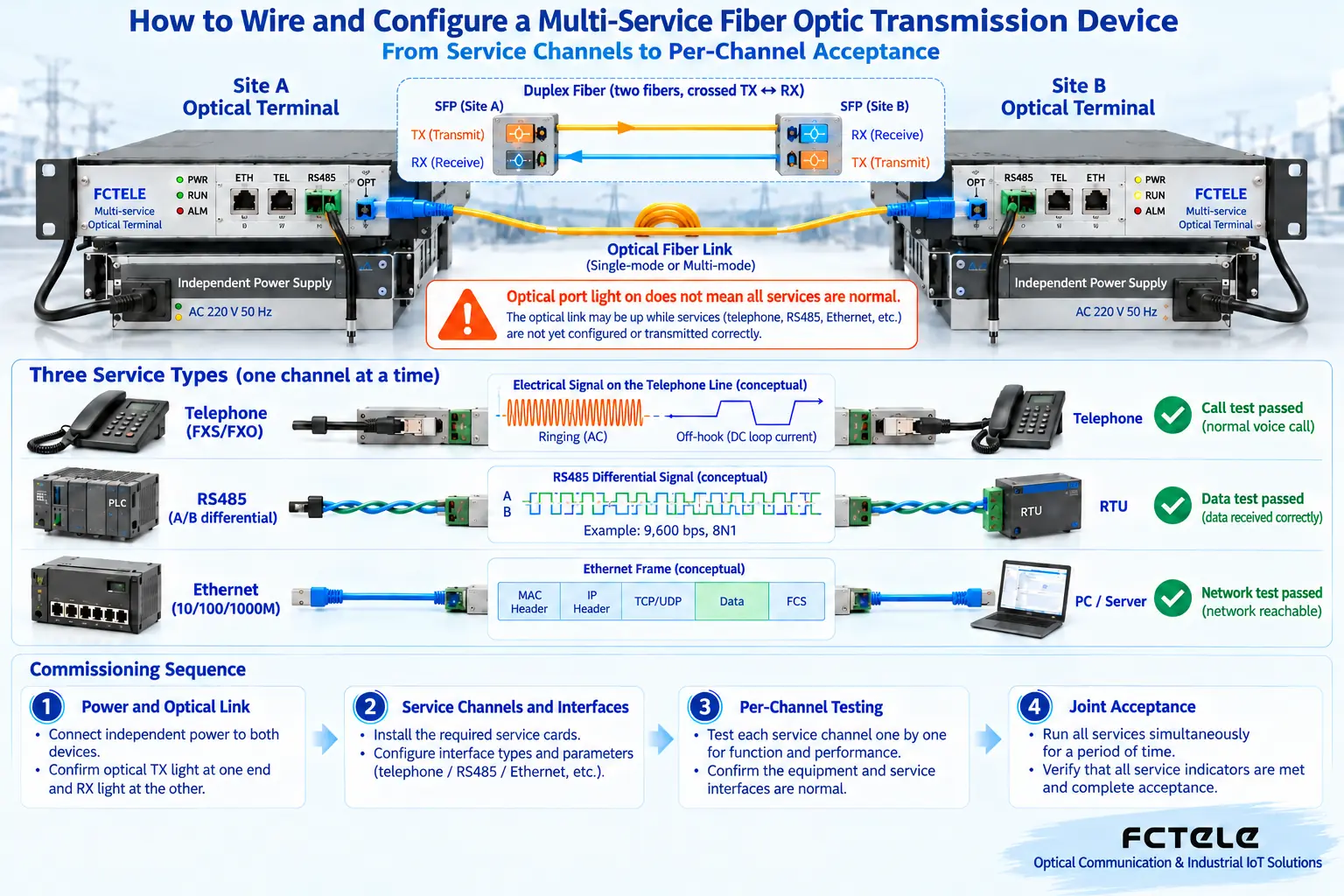
5. After a single channel works, accept concurrency and recovery
First connect one service known to be normal, and verify the whole process with a short cable and a clear port correspondence. Make an actual telephone call, verify complete request and response round trips for the serial port, and use a real application or controlled test for the network to check throughput and packet loss; if there is video, check the picture, format and control signal. After confirming each channel one by one, connect the other channels to avoid stacking multiple faults together.
Then run the planned services at the same time and observe error counters, alarms, service interruptions and latency. Success on a single channel does not prove that the shared capacity is sufficient. Save the configuration and verify restart recovery during an approved maintenance window; if the actual configuration includes a protection link, test failover and recovery separately, and do not randomly unplug fibers during production calls or control tasks. The acceptance record includes the configuration at both ends, received power, load conditions, abnormal phenomena and test results.
6. When a fault occurs, trace back along the same link
If all services fail at the same time, first check the power, optical path and common parts of the equipment at both ends; if only one channel fails, first check that service card, the corresponding channel, wire sequence and terminal parameters. If the network port lights up but the application does not work, continue checking VLAN, address and application conditions; if the serial port has activity lights but data is wrong, continue checking the electrical interface, format and protocol; if the telephone has sound in only one direction, separately confirm the line role and transmit and receive at both ends.
Do not troubleshoot by repeatedly restoring factory settings. Back up first, then test item by item; if you cannot locate the problem, submit the model, card type, port mapping, alarms at both ends and reproduction steps. For the specific meaning of indicator lights, refer to Layered judgment of power, optical path, services and alarms, and for capacity and procurement conditions, refer to Multi-service fiber optic transmission device selection and performance evaluation.
References:Feichang Technology modular multi-service telephone fiber optic transmission device product categories, corresponding product details and service card descriptions. This article explains general mechanisms and does not replace specific equipment manuals. The illustrations are technical principle diagrams, not physical wiring photos or product capability commitments.
Translated from the Chinese technical article. Source first published: 2019-07-05. Source last revised: 2026-10-13T19:15:07+08:00. Read the Chinese source
