


Maintaining a fiber optic transmission device is not about regularly opening the device and wiping it down. It is about keeping the power supply, heat dissipation, fiber end faces, and service connections in a verifiable state. First record a normal operating baseline, then maintain based on changes. When a fault occurs, check section by section. Do not rely on frequent power cycling or blindly replacing equipment to make a judgment. This article explains daily inspections for outdoor cabinets and centralized equipment rooms separately.
1. A normal record is more useful than “it looks fine”
Create a record corresponding to the device number, including model, pairing at both ends, input and output services, power supply specifications, fiber destinations, alarm status, and the most recent service test. If the device provides trustworthy temperature or optical power readings, also save the ambient conditions and load at that time. For devices without such management functions, do not fabricate page screenshots. Simply record using appropriate instruments and service results.
A baseline is not a single random value. It is a reference obtained under known configuration and stable operating conditions. Later, if you find intermittent screen interruptions, slower serial port responses, or changes in alarms, you can compare with the previous state to narrow down the scope. One light being on neither proves long-term stability nor distinguishes problems in the optical path, electrical port, or application.
2. Why heat needs to pass through the enclosure and then into the air
Chips and power supplies generate heat during operation. Heat first transfers through the circuit board, thermal conduction structures, or metal enclosure, and is then carried away by air flow and other heat exchange methods. If the area around the device is packed with cables, vents are blocked, or the temperature inside the cabinet rises, this path is restricted. Polishing the enclosure without addressing the thermal environment inside the cabinet usually cannot solve the root problem.
For rack-mounted equipment, empty slots, spacing, and air ducts should be arranged according to the manufacturer’s requirements. You cannot universally specify “leave one slot empty every few slots.” Some chassis rely on specific air ducts to operate, and removing panels without authorization may change airflow. Outdoor cabinets need to consider both waterproofing and heat dissipation. Adding fans also requires checking power supply, filtering, maintenance, and protection. Do not treat ordinary open ventilation holes as the answer for all sites.
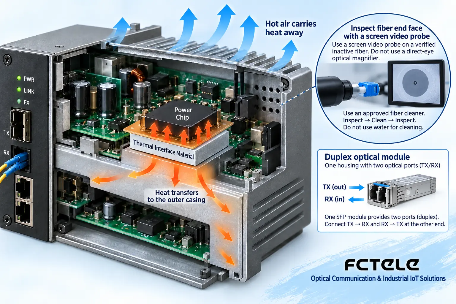
Moist air encountering a sufficiently cold surface may condense. Therefore, after the device cools down or after temperature differences change, pay attention to water ingress and moisture conditions in the cabinet. If you find moisture, unusual odor, obvious overheating, or burning, stop use according to safety procedures and have qualified personnel handle it. Do not open the power supply section and wipe it while it is energized.
3. Power supply and surge checks must follow safety boundaries
First check the nameplate and power adapter. Do not choose the same voltage just because the devices are all used for surveillance. Loose cables, corroded contacts, and insufficient power capacity may cause the device to restart when the load changes. Record the conditions under which the fault occurs and check the corresponding power supply path. Do not blame all restarts on the fiber.
Fiber optic transmission media do not have the same type of electrical path conducted by copper conductors, but the equipment is still connected to power, metal cabinets, and service copper wires. Therefore, you cannot claim that the entire system is immune to lightning strikes. Surge protection and equipotential bonding must be implemented according to site design, interface specifications, and local regulations. Do not copy a fixed grounding resistance value, and do not short all signal grounds to protective ground yourself. Different devices may have different insulation and grounding schemes.
4. Why fiber end faces affect services
Connectors align two sections of the optical path. Particles, oil contamination, or scratches on the end face may block part of the light, cause scattering, or change connection quality. The problem does not necessarily appear as a complete failure. Sometimes it reduces margin, causing the link to show abnormalities only after other conditions change. Putting on a dust cap does not mean the inside of the cap or the end face is always clean.
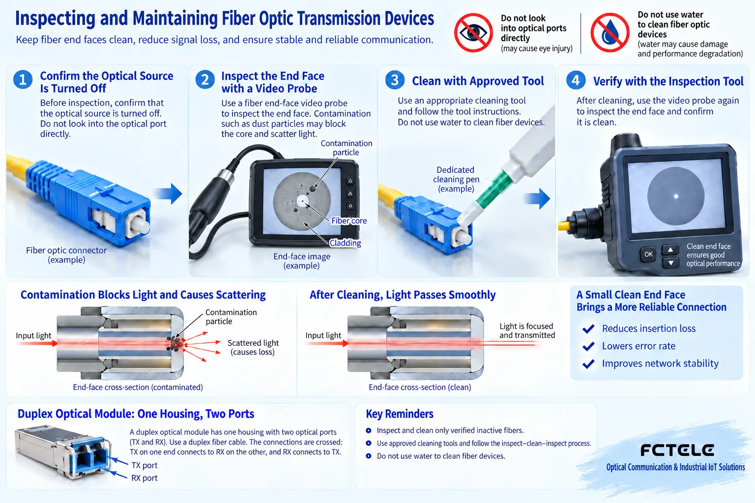
The operation follows the idea of inspect, clean if necessary, then inspect again. Use professional tools compatible with the connector and follow the tool and equipment instructions. Do not wipe the end face with ordinary paper towels, fingers, or random solvents. Unsuitable materials may leave debris or cause damage. Confirm laser risk control measures before inspection. Do not assume there is no light just because you cannot see it. It is strictly forbidden to look directly into the optical port with the naked eye.
5. After maintenance, return to the real service
Before replacing a patch cord, label both ends and take photos. Record the original transmit and receive directions. Dual-fiber usually requires the local transmit to connect to the remote receive. Single-fiber solutions must confirm that the optical configurations at both ends are complementary. Single-mode, multimode, connector polishing methods, and optical standards should all match. Do not force incompatible combinations together with adapters.
After cleaning, check that connections are secure and bend conditions are acceptable, then retest the original service. For video, check moving scenes, synchronization, and recording. For control data, check commands and responses. For telephone, check the call process. If only the optical light recovers but the service is still abnormal, continue checking the electrical port and the remote configuration. During maintenance, try to change only one condition at a time and save the results before and after.
6. Arrange inspections by risk, not by mechanical tinkering
In outdoor locations, places with a lot of dust, obvious vibration, or large temperature differences, the focus and frequency of checks are usually different from those in a stable equipment room. The cycle should be set based on the environment, fault history, and maintenance policy. Not all connectors need to be plugged and unplugged according to a calendar, and not all devices need to be restarted every day. Excessive operation instead increases the chance of misconnection and contamination.
Feichang Technology’s video series can be selected in desktop or centralized rack forms according to the scenario. Maintenance records should clearly state the actual ordered version and power supply arrangement. Shared chassis power may affect multiple services. Before maintenance, first identify the scope of impact, and arrange a window and backup plan. If repeated alarms are found during inspection, do not just reset to clear them. Also retain time, service, and environmental evidence for technical support.
A handover record should explain what was checked, what was changed, what method was used to confirm recovery, and what residual risks remain. This way, the next maintenance person can continue the judgment instead of trying all switches again. The value of maintenance is to reduce avoidable uncertainty, not to promise that equipment will never fail.
References Cisco fiber inspection and cleaning procedures and Feichang product details. The illustrations are general principle diagrams, not actual measurements or electrical construction drawings.
Translated from the Chinese technical article. Source first published: 2018-12-04. Source last revised: 2026-10-13T19:15:07+08:00. Read the Chinese source
