


Several sites are distributed along a road, tunnel, or pipeline, and all need to send services back to a center: should each site use its own independent optical link, or should intermediate devices add sites one by one and share a trunk line? This is the core of choosing between node-based and point-to-point optical multiplexers. Point-to-point usually makes it easier to locate faults by separating links; node-based is suitable for aggregation along a route, but it requires checking shared capacity, power supply for intermediate devices, and the scope of fault impact at the same time. No single topology saves more fiber and is more reliable at every site.
1. First understand what “node-based” describes
An optical multiplexer converts services on electrical interfaces into signals suitable for optical fiber transmission, and restores the corresponding interfaces at the other end. A point-to-point solution connects a pair of endpoints; a node-based solution places access devices along the route so that local services can join the trunk line, or specified services can be dropped from the trunk line. Terms such as “bus type” and “chain type” in older documents are often used to describe this site-by-site access method, and do not mean that the device has only one internal implementation.
You also need to ask clearly what the service object is. Analog video node devices, serial ring network optical multiplexers, and Ethernet cascade devices may all be called “nodes” in speech, but they process different signals, and their center devices, service channels, and management methods are also different. You cannot assume they can interconnect just because they all have two optical ports; even less can you directly treat a node-based video device as an optical network unit for broadband access. Whether it belongs to the Synchronous Digital Hierarchy must be checked against the standards and interfaces supported by the model, not just the word “node.” ITU-T G.707 What is discussed is the SDH network node interface, and this cannot be used to label all chain-type optical multiplexers as SDH.
2. Point-to-point and chain aggregation differ in path and shared resources
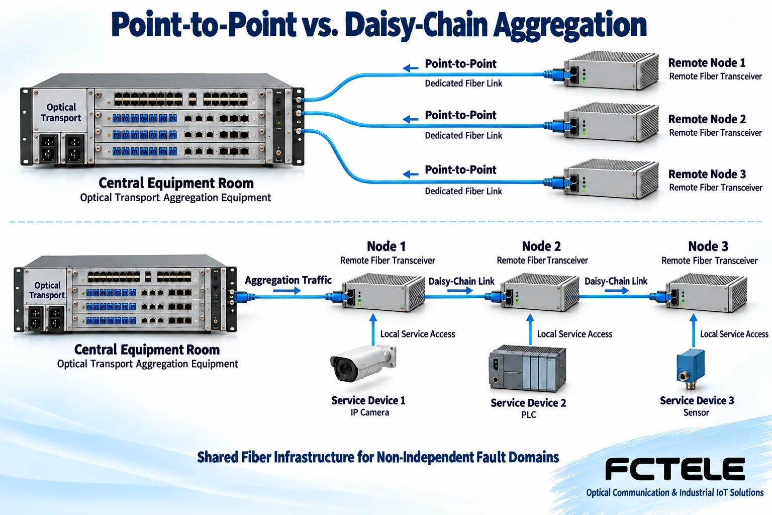
In a point-to-point solution, each remote end has a corresponding center link. A fault in one link usually affects only that pair of endpoints, provided they do not jointly depend on the same power supply, chassis, or damaged optical cable. In a chain solution, services from farther sites pass through intermediate nodes to reach the center; the trunk segment closer to the center carries the services of multiple sites, and path and equipment faults may affect later sites at the same time.
When sites are distributed along the same road and the site can provide power for intermediate nodes, sharing the route may reduce the fiber cores and interfaces needed for independent returns to the center. But when sites are scattered, sufficient fiber cores already exist, or maintenance personnel want to check each link independently, point-to-point is not necessarily a waste of resources. You should compare actual route length, occupied fiber cores, center ports, on-site power supply, and maintenance cost, not just the number of devices. The arrows in the figure only indicate the upstream service aggregation direction; actual bidirectional communication also requires matching optical ports and channel arrangements.
3. How local services join the data stream in the fiber
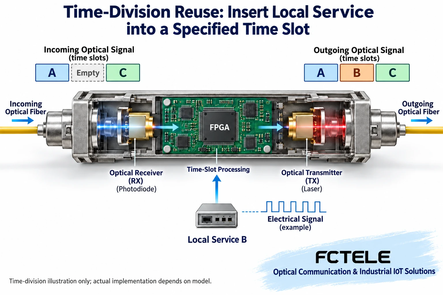
Taking digital optical transmission equipment using time-division multiplexing as an example, multiple services do not squeeze into the same time position at the same time; instead, they occupy different time periods according to an agreement, and these positions are called time slots. Only after the receiving end finds the frame boundary and time slot positions can it separate the various data streams. A node receives upstream data, adds local data at the specified position, and continues to transmit other channels; when local output is needed, it extracts the service assigned to the local site. This type of add and drop process is often called add/drop.
Figure 2 replaces a reserved empty position with local service B, while the original positions of A and C remain unchanged. It expresses channel assignment, not that the device can increase trunk bandwidth out of thin air. Real products may use different frame formats or other forwarding mechanisms, so the manual should be checked. Electrical interface isolation solves electrical problems such as ground loops; time slot separation solves the problem of service identification; neither means that each service has completely independent fiber and fault paths.
When transmitting analog video, digital equipment usually also needs to sample and quantize the continuous electrical signal, and the receiving end then restores the output. Whether compression is used depends on the encoding method. “Uncompressed” does not mean zero delay; sampling, frame processing, electronic circuits, and fiber propagation still take time. The pulses in the figure are only an illustration of digital electrical signals, not measured waveforms, and cannot be used to derive the sampling rate or picture quality of a particular model.
4. Node count, channel count, and distance must be calculated together
First list the interface type, quantity, direction, and rate of each site, then check whether the center can receive and output all services. The number of video channels, serial channels, and Ethernet ports are not the same capacity unit. The common segment close to the center must accommodate all services passing through it, and frame overhead and protection arrangements must also be considered. The nominal rate of an optical port is also not equal to the total usable service capacity, and the number of video channels cannot be directly calculated from it.
Numbers such as “supports ten video channels” and “up to sixteen nodes” are meaningful only in the corresponding platform and configuration, and are not universal limits of node-based equipment. Expansion may also require matching center boards, node versions, and channel configurations. If a newly added node occupies an existing service position, even if the optical link lights up, it cannot be considered a successful expansion. Before installation, a complete channel table should be made, noting where each site joins and where it outputs.
For distance, check the fiber type, transmit power, receive sensitivity, maximum receive overload, and connector loss segment by segment. A node that receives and retransmits with power can divide the optical power budget into several segments, but cumulative delay and system-level limits still exist. If the device switches to optical bypass after a power failure, two segments may become a longer straight-through segment, and the loss margin must be recalculated. Single-fiber, dual-fiber, and wavelength pairing are also determined by the optical port configuration, and cannot be judged only by how many sockets are on the housing.
5. Power-off bypass and ring protection are not the same thing
If an ordinary active chain node loses power, the receive and transmit circuits may stop working, and services at the far end may be interrupted. Some devices have optional optical bypass, allowing the optical signal to bypass the powered-off device and continue propagating; this cannot restore the services of the powered-off node itself, nor can it repair a cut fiber. Whether bypass is available, the loss in bypass state, and the applicable connection method all need to be verified separately.
Ring protection requires another available path and corresponding control mechanism. Whether services can be re-established after a fault, how long recovery takes, and whether data is lost during the period must be verified in combination with the model and application. Two fiber cores placed in the same easily damaged optical cable may still fail at the same time; two power terminals connected to the same upstream power supply cannot eliminate the risk of shared power supply. Nodes distributed in multiple locations do not automatically bring redundancy by themselves.
6. Use Feichang Technology serial ring network products to check real capabilities
Feichang Technology Fiber self-healing ring network serial optical multiplexer category , in SRing2004 product page , capabilities such as independent serial channels, dual optical paths, chain and ring topologies, interface isolation, and redundant power supply are listed. For serial acquisition along a route, optical links and electrical isolation can help deal with distance and ground loop problems, while the backup path serves recovery after a link fault.
But this is an example of a serial service product, not proof of the specifications of a video node device. Selection still requires confirming the interface standard, channel mapping, device matching relationship, and protection conditions, and video, telephone, or Ethernet capabilities cannot be added to this model as a side effect. Power supply parameters should be checked against the nameplate and manual of the delivered model; node counts, management functions, and lossless switching promises without clear basis should not be written into acceptance criteria.
7. How to accept a route project
Assume three on-site stations each have acquisition services to be sent to the same center. First decide whether the service is video or serial, then choose the corresponding device system; the same topology diagram cannot replace interface confirmation. Record all node locations, fiber core numbers, channels, and power supply sources. Connect site by site, check whether the newly added service correctly reaches the center, and confirm that the original channels have not been overwritten.
Then check errors, delay, and continuity while all services are running at the same time, not just a single channel or no-load state. Record a normal baseline according to the alarms and test interfaces the device can provide. Within an approved maintenance window, test one link or one power supply fault, observe which sites are affected, whether protection takes effect, and the service correspondence after recovery; do not randomly pull cables in a production system for testing.
Troubleshooting starts from the scope of impact: if a single electrical interface is abnormal, first check the wiring and channel configuration; if a node and everything after it goes offline together, first check the common optical segment and the power supply of the intermediate node; if some services are misaligned after protection, recheck the mapping. When cleaning and inspecting optical connectors, do not look directly into the optical port, and operate power supply and grounding according to safety regulations. The final deliverable is not just a screenshot showing “it connects,” but also a channel table, link budget, fault test records, and service verification results after recovery.
Document note: The main text was checked against the above Feichang Technology product category, model details, and ITU standard scope. The two schematic diagrams are general teaching illustrations, not actual product photos, customer cases, or performance measurements. The simplified devices in the figures do not represent the specific appearance and internal implementation of SRing2004.
Translated from the Chinese technical article. Source first published: 2019-08-28. Source last revised: 2026-10-13. Read the Chinese source
