


Conclusion first
A distant instrument can be connected back, relying on a complete information chain
To read a serial instrument in another building from the control room, a matched pair of serial fiber converters can replace the long copper cable in between: the near end receives the serial electrical signal, the fiber sends the corresponding information to the far end, and the far end outputs an electrical signal that the instrument can recognize. It is also often called a serial fiber modem. The original control software still needs to send the correct commands, and the instrument still needs to reply according to the original protocol.
First distinguish three things: the reading is information, the change in voltage or light intensity is the signal that carries the information, and the copper cable or glass fiber core is the transmission medium. Changing the medium is not changing the business language. This article uses light intensity changes and direct detection to explain the general mechanism. It does not treat a teaching cutaway as the real internal circuit of a specific model, nor does it claim that all fiber modems use the same encoding.
The entrance first recognizes electrical signals; copper wires cannot be connected directly into glass
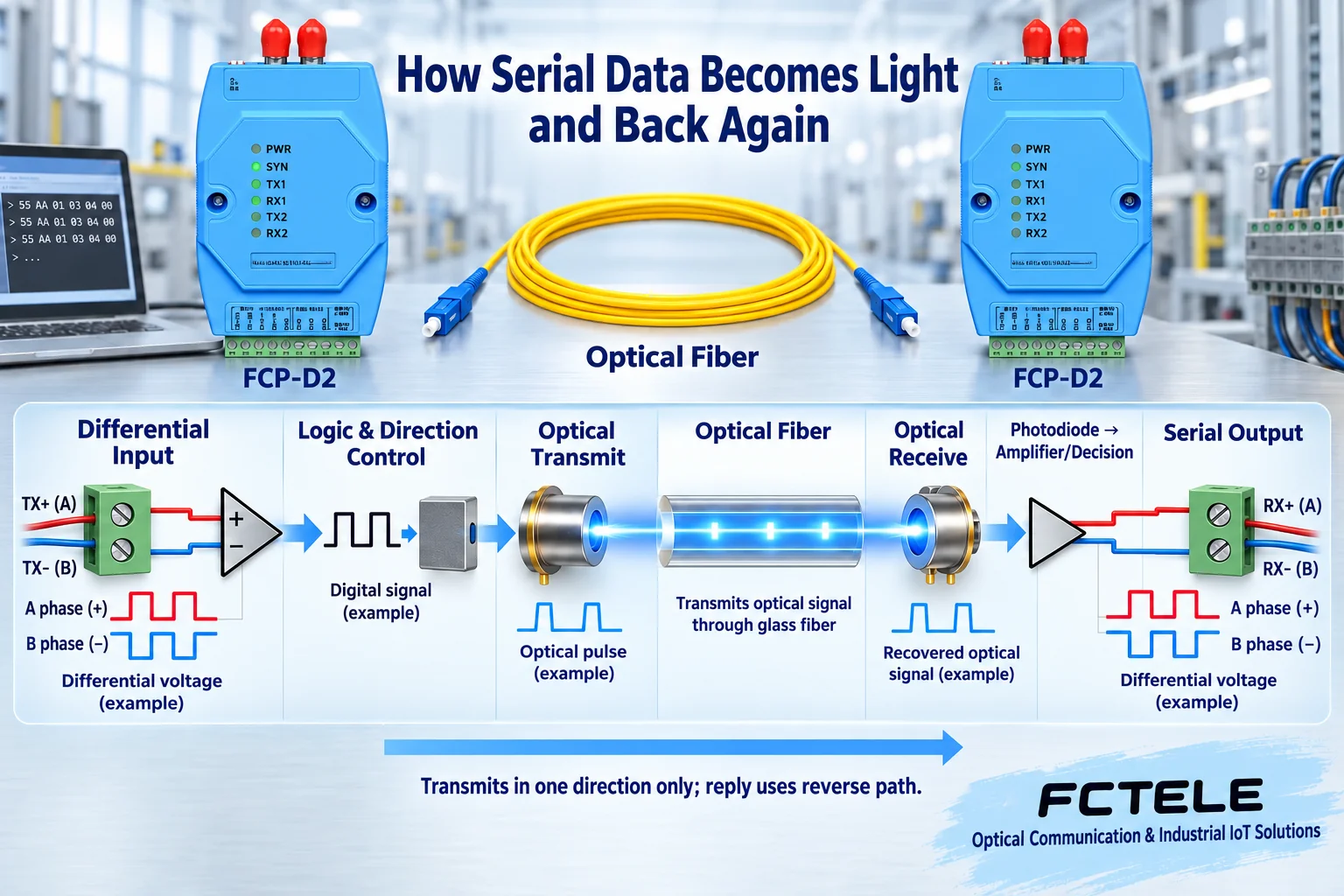
RS232 receivers mainly recognize line voltage relative to a reference ground; RS422 and RS485 receivers mainly compare the voltage difference of a differential pair. The corresponding electrical front end obtains a processable logic state, and then internal circuits organize transmission according to the product design. This is not resampling an analog temperature: the instrument has already generated serial data, and the fiber modem is responsible for extending the matched service.
RS232 three-wire data and interfaces with handshake signals must be checked separately; RS422 commonly uses independent transmit and receive pairs; two-wire RS485 commonly uses time-shared transmission and reception. A DB9 or green terminal block is only a shape and cannot prove that the pins, wire count, and control signals are consistent. Comparing terminal definitions, modes, and both manuals is more reliable than guessing the wiring by interface color.
Drive the light source so that changes in light carry information
The optical transmitter needs a driver circuit. Taking simplified light intensity modulation as an example, the circuit makes the emitted light change according to the information; the light enters a suitable glass fiber core and propagates along the optical path to the other end. A light pulse is not turning bytes into little glowing balls, and it does not have to be visible to the naked eye. Do not look directly into the optical port; use suitable electronic tools to inspect the end face.
There may also be encoding, channel organization, clocking, or buffering inside, and the actual structure varies by model. Transparent transmission cannot lead to the conclusion that there is no internal processing, and it is even less equal to copying the noise, current, and waveform on the input copper wire point by point. The teaching diagram shows the signal change relationship and does not assign a line code or coherent reception algorithm to an unknown product.
Direct detection: first obtain a tiny electrical signal, then restore the serial output
The light arriving at the far end illuminates a photodetector and can form a photocurrent. The receiving circuit then amplifies, recognizes, and restores the state that needs to be transmitted, and finally hands it to the corresponding serial driver to establish the electrical output required by the terminal. The photocurrent itself is not a ready-made RS485 voltage, and it cannot skip the output driver and connect directly to the instrument.
The receiver must recognize the signal under allowed conditions. If the input is too weak, it may be impossible to distinguish the signal from noise; if it is too strong, it may exceed the receive range. More power is not always better, and short-fiber testing of a long-distance version must also check for overload. Only when transmission, reception, wavelength, fiber type, and loss all match is there a foundation for stable operation of the optical path.
The optical path is bidirectional, but that does not mean two-wire RS485 can transmit simultaneously
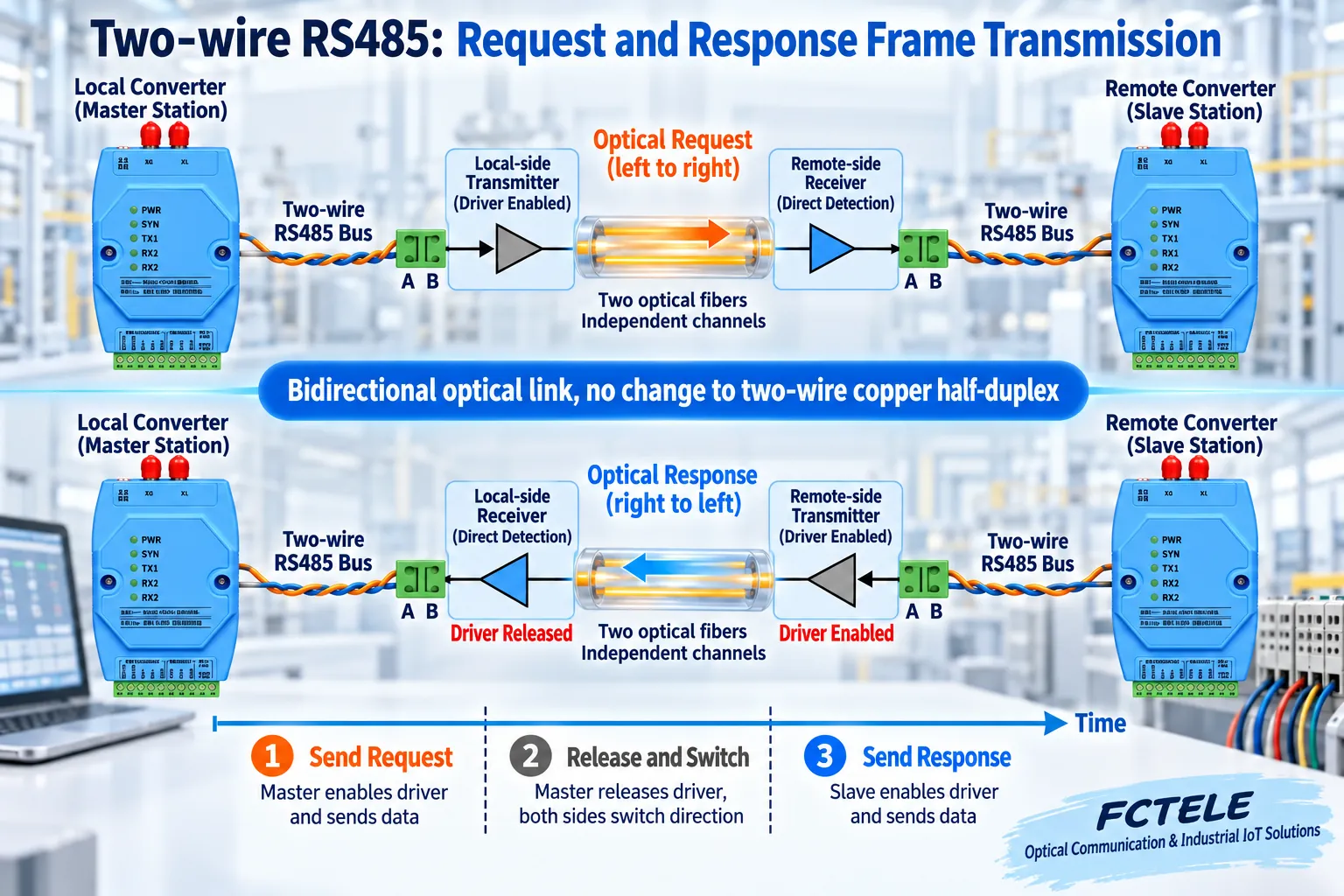
Dual fiber usually uses two fiber cores to handle the two directions separately, with local TX connecting to remote RX; single-fiber bidirectional uses a corresponding optical configuration pairing and cannot simply copy the dual-fiber wiring. The optical side has a reverse path, but the copper side must still follow the transmit and receive rules of the interface used. Two-wire RS485 shares one pair of wires, and uncoordinated simultaneous driving by both sides can still cause conflicts.
In a common polling scenario, the master releases the transmit occupancy after sending a request, and only then does the slave have a chance to reply. Releasing too early may cut off the last character, and releasing too late may block the first part of the response. Automatic direction control helps complete the switch, but it still needs to be verified with real parameters and messages. Termination, biasing, reference potential, and stub conditions will not be automatically fixed by the fiber.
How Feichang Technology’s multi-channel and cross functions are used in a clear task
FCP-D2 official website information separately describes RS422/485 and three-wire RS232 channels, and also lists channel crossing between two units and single-unit interface conversion functions. If the local end is RS232, the far end is RS485, and the service messages are originally compatible, the required mode can be checked against the delivery documentation. This is a specific product function, not a default capability of all fiber modems.
Before connection, make a correspondence table that clearly states the local channel, remote channel, serial standard, DIP switches, pins, and signals to be transmitted. Adjacent terminals do not mean they belong to the same channel, and providing three types of interfaces does not mean there are three independent channels. Different service protocols still require software or an explicitly supported gateway, and cannot rely on cross mode to translate instrument commands.
After switching to fiber, the original character speed and power constraints remain
For example, at 9600 bit/s, 8N1 format, one character includes a start bit, eight data bits, and a stop bit, totaling ten bit times, about 1.04 milliseconds. This is a teaching calculation. The instrument still outputs at the set rate, and the fiber will not automatically turn it into a gigabit interface; overall polling also includes processing, propagation, direction switching, and waiting.
The fiber data segment does not rely on a conductive path to transmit information, nor does it automatically supply power to the remote device. Power supplies at both ends, short copper cables, enclosures, and metal components of the optical cable still need to be managed according to installation requirements. The dielectric characteristics of the glass fiber core are not equal to whole-device isolation certification, and even less can they lead to absolute lightning protection, arbitrary distance, or automatic encryption.
From the original direct connection to short fiber, then to the formal line
First confirm on a controllable short copper cable that the controller and instrument can complete requests and replies, and save the known-correct messages. Add the same pair of converters and suitable short fiber, keep the terminal parameters unchanged, and check the mode, channels, and bidirectional output; finally connect the formal optical cable and record the end face, power, and service results. Change only one condition at each step so that the fault scope is clear.
If short fiber also fails, first check power, standard, character format, and direction; if the request reaches the far end but cannot come back, separately confirm whether the instrument replied, whether the bus was released, the reverse optical path, and the master timeout. A lit lamp can only prove partial activity; it cannot prove that the returned data is correct.
Delivery should be able to reproduce one correct question-and-answer exchange
Acceptance should at least save the model and version, optical pairing, terminal table, channel table, serial parameters, normal requests and responses, and continuous polling and recovery test conditions. Read-type and execute-type services should be verified separately, and write operations should also confirm whether retries cause duplicate actions, rather than only looking at the connection status of one link.
Maintenance personnel should be able to determine from the records whether the problem belongs to electrical input, optical path, direction control, or application protocol. Explaining the complete signal chain clearly and then verifying it with real service evidence is what makes serial fiber conversion successful; similar optical ports, a blinking transmit lamp, or the instrument displaying one number cannot alone replace this conclusion.
Documentation note: The illustrations are general mechanism diagrams and have been technically checked; appearances marked with a model refer to official website photos, and other cutaways and components do not represent the internal circuits of actual Feichang Technology products. They are not measured waveforms or real project sites; wiring and power supply are subject to the delivery manual.
Verification materials: Feichang Technology FCP-D2 two-channel serial fiber modem
TI RS485 Design Guide
FOA Optical Link Budget
Translated from the Chinese technical article. Source first published: 2020-01-02. Source last revised: 2026-10-13. Read the Chinese source
