


When one optical port at one end is lit and the other end is dark, or both ends are dark, you cannot directly judge which optical module is broken. The meaning of the light is defined by the device, and the transmit and receive optical paths at the two ends may each have separate problems. Troubleshooting should first confirm the support relationship between the module and the port, then check transmission, fiber, reception, and upper-layer services separately. Do not immediately force the rate, repeatedly unplug and plug, or connect the transmitting light directly to the receiving port.
1. Why the two ends may show different states
A common dual-fiber link has two independent directions: the transmitter at end A goes through one fiber core to the receiver at end B; the transmitter at end B goes through the other fiber core to the receiver at end A. One direction working normally does not guarantee that the other direction works normally. A damaged fiber core, a single transmitter being shut down, or the receiving conditions at one end not being met can all produce an asymmetric state. If you think of the two fibers as one “network cable,” it is easy to miss this difference.
A single-fiber bidirectional link has only one physical fiber core, but it still has two communication directions, usually distinguished by complementary wavelengths. The pairing requirement is not that the labels on the two modules are exactly the same, but that the transmit wavelength and the receiving conditions at the opposite end match each other. The actual wavelength, rate, and distance specifications should be confirmed according to the model; do not apply one set of example wavelengths to all single-fiber modules. Also check the interface and fiber type.

2. Preserve evidence first, then change the site
Record the device models at both ends, port numbers, complete module model, current alarms, fiber type, and the original service symptom. Check whether the host is powered and whether the port is enabled, and confirm that the module used is supported on that host model and software version. The fact that the shape can be plugged in only proves that the mechanical structure is close; it does not prove that the rate, electrical interface, or vendor compatibility requirements are all met.
If the problem has just occurred, first ask whether a module, patch cord, or configuration was recently changed. Even if a new module is marked with the same rate, it may have different fiber requirements or transmit/receive pairing. Do not modify multiple settings at both ends at the same time just to try things out. The maintenance window, backup, and rollback methods should be clarified first, especially when the remote device can only be managed through this link; a misoperation may make recovery more difficult.
3. Separate “there is light” from “there is correct data”
After the receiver converts light into an electrical signal, it still needs to correctly interpret the data. If the optical power is sufficient but the line rate, encoding, or service format is incompatible, a valid link may still fail to be established. Conversely, if the optical power at the receiving end is too low, it becomes difficult to distinguish the useful signal from noise. Both types of problems can appear as no connection, but the troubleshooting direction is different.
When the host supports digital diagnostic monitoring, you can record the transmit and receive optical power, temperature, and voltage at both ends, and compare them with the corresponding module thresholds. Do not copy only one receive reading, and do not directly subtract the transmit power from the receive power at the same end and treat that as the one-way fiber loss. Transmit and receive come from different directions; correct analysis must correspond to the actual transmitter and the actual receiver.
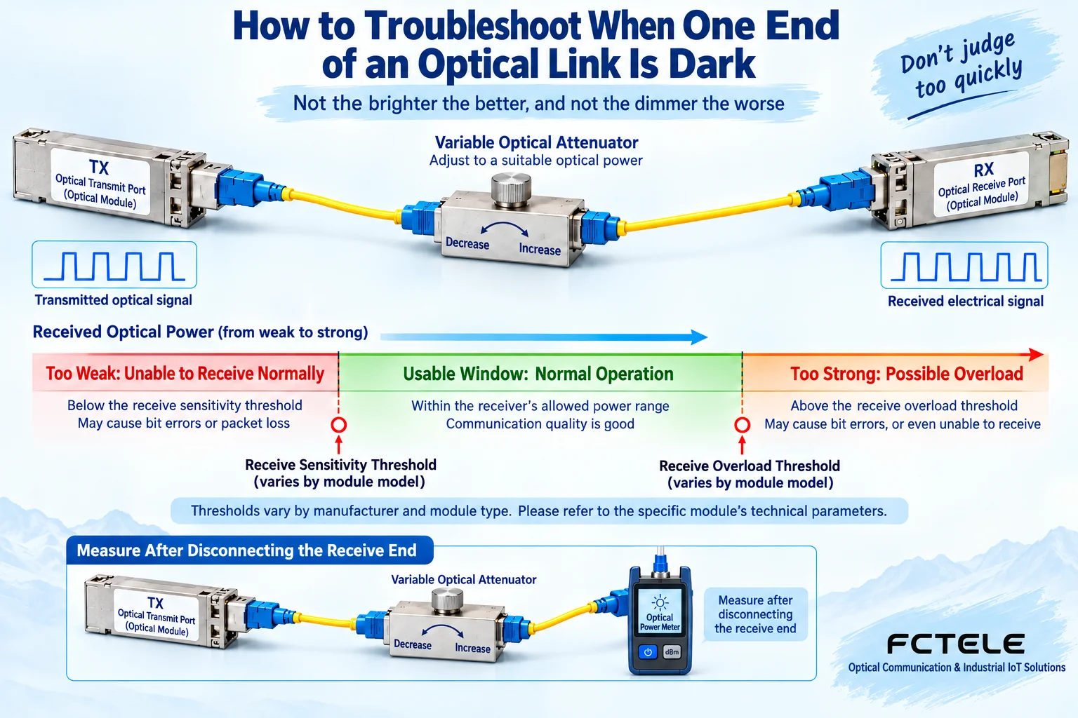
4. The receive power has a window; stronger is not always better
The receiver has sensitivity, and it also has a maximum allowed input power. Below the required range, errors may occur; above the allowed range, distortion may also occur or even risk may be introduced. When a long-distance module is connected with a very short patch cord, first check the manufacturer’s specified minimum distance, power range, and attenuation requirements; do not assume that a short-cord test is necessarily safe, and do not casually add a fixed attenuator without checking the specifications.
When measurement is needed, use an instrument that supports the corresponding wavelength and power range and is in reliable condition, and operate it according to safety procedures by personnel with the appropriate capability. An optical power meter measures the optical power reaching that position; it cannot by itself prove that the data content is correct. The instrument reading and the module diagnostic reading may differ, and they should be interpreted together with the measurement conditions and instrument error; do not treat one number as the only conclusion.
5. Then check the end face, direction, and line
For dual-fiber connections, confirm that TX connects to the RX at the opposite end, and that the other direction is also correctly paired. Do not just swap the two fibers at one end and repeatedly try your luck; number the fiber cores and confirm the correspondence between the two ends. When checking patch cords and patch panels, pay attention to connector polish type, bending, pulling force, and intermediate splices. Looking firmly connected does not mean that the end face is free of contamination or that the line has no extra loss.
Use suitable tools to handle connectors by inspecting, cleaning, and inspecting again. Do not look directly into the optical port, and do not blow on or touch the end face with your hands. If you suspect a line problem, you can, under safe conditions, replace it with a known-good patch cord or link while keeping other conditions unchanged. If an abnormality on a long-distance line needs to be located, a professional should choose a suitable test method; do not treat an ordinary continuity test as complete line diagnostics.
6. Replacement tests must be able to explain the problem
When replacing a module, use a module that is known to be supported by the host and matched to the optical conditions at the opposite end. A so-called “another good module” cannot merely be one that once lit up on a different type of host. Record the original model before replacement, and check the status and errors after replacement. Only if the fault moves with the module does the possibility of a module problem increase; if the fault remains at the port or line, you should continue checking the host and the link.
Loopback testing is also not a universal plug-in action. Some long-distance modules may exceed the receive power limit if directly looped back, and some services require a dedicated test configuration. Use it only when the model documentation clearly supports it, the power conditions are met, and the on-site personnel understand the test boundaries. This article does not provide rate-forcing commands or optical port shorting steps that are independent of the model, to avoid turning a diagnostic operation into a new fault.
7. After the link recovers, still check the service layer
After an Ethernet optical link is established, VLANs, addresses, access policies, or the service at the opposite end may still cause the service to fail. At this point, continuing to unplug the fiber will not solve a logical configuration problem. First observe the port error statistics and the actual data flow, then check the network conditions at both ends. One successful Ping only proves that a certain path was reachable at a certain moment; it cannot replace continuous service, throughput, and stability acceptance.
Feichang Technology’s FCM-OEO product uses two SFP slots for optical signal relaying or conversion, and it is not the same structure as an ordinary electrical-to-optical transceiver. Troubleshooting this kind of link requires confirming the support relationship among the two slots, the corresponding modules, and the service being carried; you cannot apply Ethernet link-light conclusions just because both are called optical modules. The service capabilities listed on the official website must also be checked against the configuration, and cannot be understood as meaning that any combination of modules will interoperate.
Reference materials:Cisco optical link troubleshooting and digital diagnostic documentation;Feichang Technology FCM-OEO product details. The illustrations are general mechanism diagrams, not measured waveforms or wiring promises for a specific model.
Translated from the Chinese technical article. Source first published: 2020-05-21. Source last revised: 2026-10-13T18:52:49+08:00. Read the Chinese source
