


Troubleshooting a video fiber optic transmission device should be located segment by segment along the path: power supply, input signal, optical link, output signal, and service control. No image, abnormal image, and PTZ control failure are not the same fault. First confirm whether the device carries analog video, SDI, network video, or another service, then choose the corresponding test tool. Do not apply one fixed set of indicator light states or optical power values to all models.
First describe accurately what is not normal
Record the abnormal channel, the time it occurred, whether all channels are abnormal at the same time, and whether it temporarily recovers after power off. If all video and control are interrupted together, first focus on the power supply, optical path, and equipment shared by both ends. If only one video channel is abnormal, first check that camera, video cable, and input/output ports. This is a method to narrow the scope, not a judgment that the device is damaged without testing.
Also distinguish the signal format: BNC is only the connector shape; inside it may be analog composite video or SDI. RJ45 is usually used for Ethernet, but may also be used by dedicated equipment for other interfaces. The port name, device model, and manual together determine the connection method. Being able to physically plug it in does not mean the service is compatible.
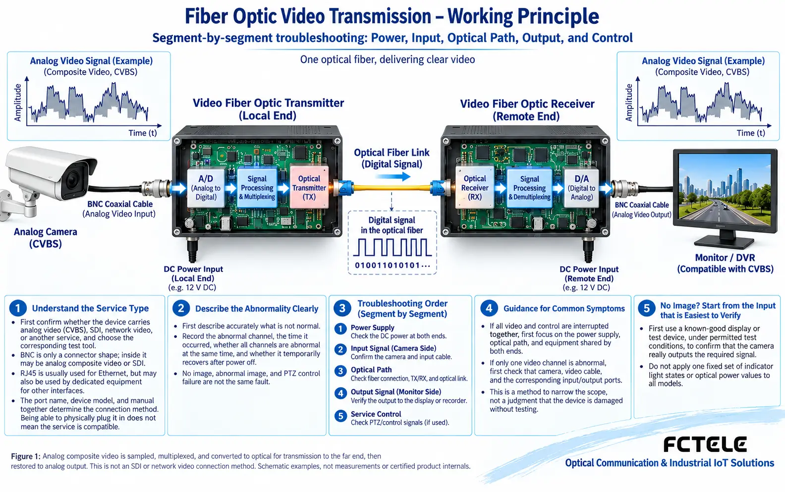
No image: start from the input that is easiest to verify
First use a known-good display or test device, under permitted test conditions, to confirm that the camera really outputs the required signal. If there is no video at the input to begin with, changing the fiber will not solve it. Then check the transmitter and receiver roles, input and output directions, and video format and rate. Some devices are fixed unidirectional transmission, while others are bidirectional or multi-service, so you must check according to the model.
Measure the supply voltage at both ends and check polarity, allowed input range, and connection reliability. A power indicator light being on only means that some part of the circuit has power; it is not enough to rule out voltage drop under load. When swapping power supplies for comparison, use a matched, known-good power supply and do it under safe operating conditions.
Optical path troubleshooting is not ‘if you see red light, it passes’
A visible-light fault locating tool can only help find continuity, obvious bends, and connection problems; it cannot replace received power measurement. Received optical power is expressed in dBm, and link loss is expressed in dB. The measured value should be compared with the model’s receive sensitivity, overload upper limit, and engineering margin. Even a very short distance can fail due to connector contamination, and too much power is also not better.
Before connecting, check the endface, clean it according to the specification, and then recheck. Do not touch the endface with your hands, and do not use ordinary tissue or unsuitable liquids as a universal cleaning method. The measuring tool should be set to the appropriate wavelength and matched with the adapter. Do not look directly into the optical port or fiber endface, and the inspection microscope should also be used according to the safety instructions.
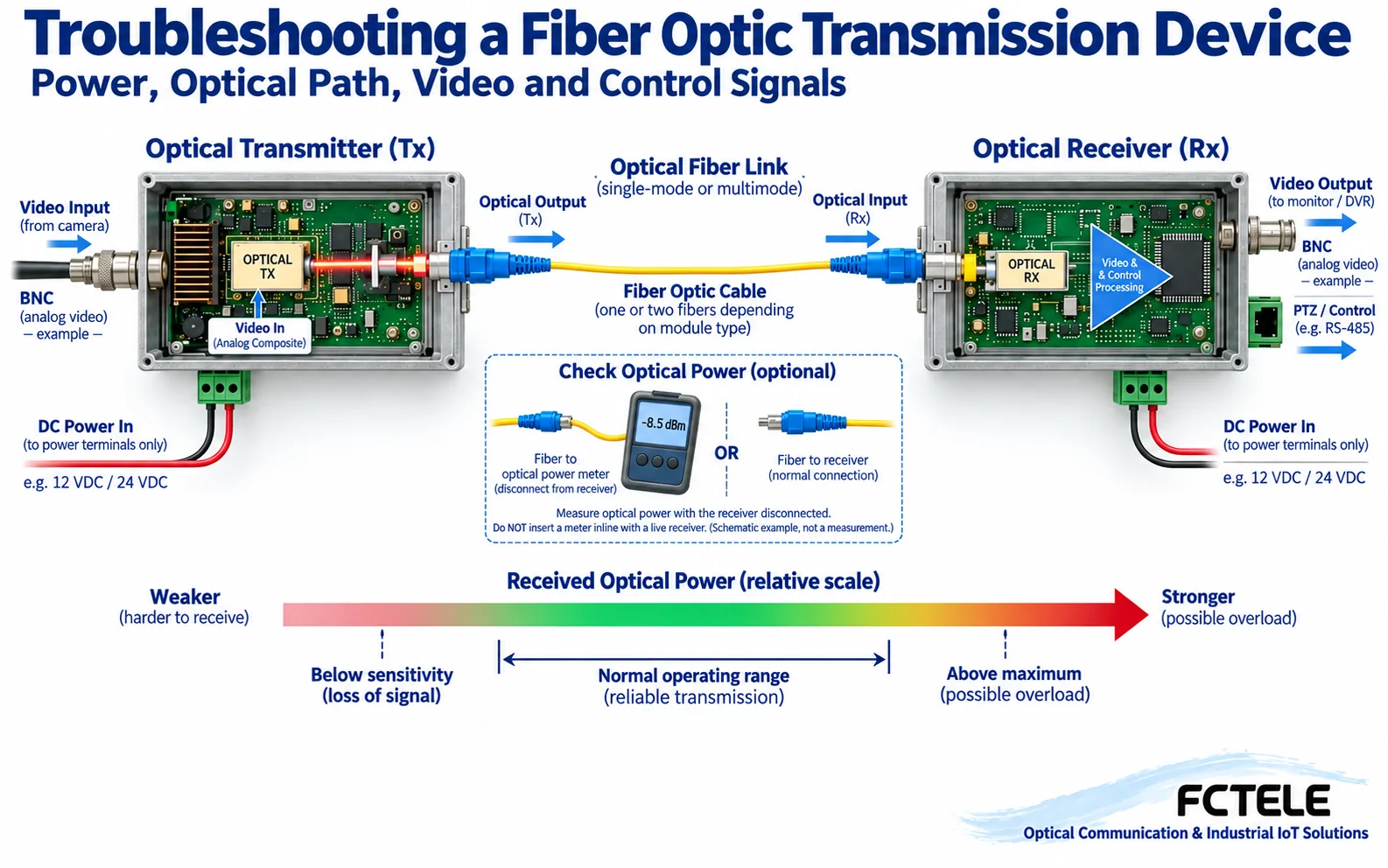
Video works but control does not: check the independent data channel
Normal video means the corresponding video path is basically established, but it does not mean the RS485 control channel is also normal. Check the controller and PTZ protocol, address, baud rate, parity method, and the fiber optic transmission device’s data direction and terminal definitions. Different manufacturers may name A/B differently, so match according to the manual definition and do not judge by ‘A must be positive’.
RS485 is mainly a differential electrical interface and does not automatically define PTZ commands. Wiring should be designed together with bus topology, termination matching, biasing, and the device common-mode range. Seeing a certain static voltage between A/B with a multimeter cannot directly prove that the data message is correct; when necessary, use serial logs, protocol analysis, or suitable oscilloscope testing.
How to preserve evidence for image tearing, intermittent video, and intermittent faults
Intermittent video may be related to input cable quality, format mismatch, optical link margin, power supply fluctuation, or interface failure. First use a short-distance, known-good cable to establish a baseline, then replace only one factor at a time. Record the phenomenon before and after replacement, rather than continuously replacing multiple devices and losing the source of the fault.
If the abnormality accompanies motor start/stop or thunderstorms, check the power supply, transient interference introduced by copper cables, grounding, and protection measures. The fiber itself does not form a metallic conductive path, but power lines and service copper lines may still introduce interference; therefore you cannot claim that the whole device is naturally immune to lightning. Work involving strong current, lightning protection, and grounding rectification should be handled by qualified personnel.
After recovery, perform continuous service testing and verify each video channel, bidirectional control, and power-off recovery. Hand over the model, topology, optical power, power supply, abnormal time, and handling records to maintenance personnel, so that the next similar problem can be compared with the normal baseline. When the fault does not recur, state the observation conditions and do not treat one recovery as a permanent solution.
References:Fluke Networks: Fiber endface cleaning and inspection. Formal acceptance also requires the interface specifications and test requirements of the corresponding equipment.
Why ‘having light’ may still mean no picture
Take digital optical transmission of analog composite video as an example. The camera first generates a continuously changing voltage signal. The transmitter samples and encodes it over time, multiplexes it, and then sends it to the optical transmitter. The receiver converts the light back into an electrical signal, completes synchronization and demultiplexing, and then restores the video output. This path includes input, conversion, link, and recovery stages. What an optical power meter sees is only the optical energy reaching the measurement point; it cannot determine that the video format is correct, that synchronization has been established, or that the output channel is connected correctly.
SDI is itself digital serial video and requires compatible equalization, clock recovery, and interface processing. Network cameras involve Ethernet, addresses, streaming media, and decoding. They cannot share the ‘snow judgment method’ of analog video. Therefore, when you see a black screen, first confirm the service object, then choose the test tool. A multimeter can measure power under permitted conditions, but a single static voltage on the video line cannot prove that the video is valid.
How to separately verify intermittent noise and control failure
If it is normal during the day and abnormal at night, first record the time when the camera fill light turns on, the power supply load, and the abnormal range. Do not rush to conclude that it is caused by the fiber cable length. If control is lost when the motor operates while the picture is still present, first record changes in the copper control path and the power supply side. If the picture and control are interrupted at the same time, then further observe the power supply and optical path they share. The related phenomena can only determine the test order; they cannot directly replace fault evidence.
Do an approved short-link test: keep the equipment at both ends, the configuration, and the compatible video source unchanged, and replace only the on-site optical path with a known-good test link with suitable power conditions. If the fault disappears, then check the patch cord, endface, patch panel, and backbone section by section. If the fault remains, then replace the input cable, power supply, or device one by one. Short patch cords also need to be checked for overload risk; do not apply the same attenuator to all models.
Check the interface list for corresponding Feichang Technology products
Feichang Technology FCV-V4T/R four-channel integrated multiplexing video fiber optic transmission device The materials list video and data status indications and optional multi-service configurations. During maintenance, the actually ordered interface list should be clearly listed and then accepted channel by channel. A product series offering an optional service does not mean that every on-site unit is equipped with the corresponding interface. The specific power version, video format, and optical port pairing must still be based on the delivery materials.
Note: The illustrations are general principle diagrams, not actual product cross-sections, on-site measurements, or certification proof. Interfaces, power supply, firmware, and safety conditions are subject to the actual model manual. Strong current, live measurement, lightning protection, and grounding rectification should be handled by qualified personnel.
Translated from the Chinese technical article. Source first published: 2019-09-12. Source last revised: 2026-10-13T17:22:03+08:00. Read the Chinese source
