


First, define the communication scope discussed in this article
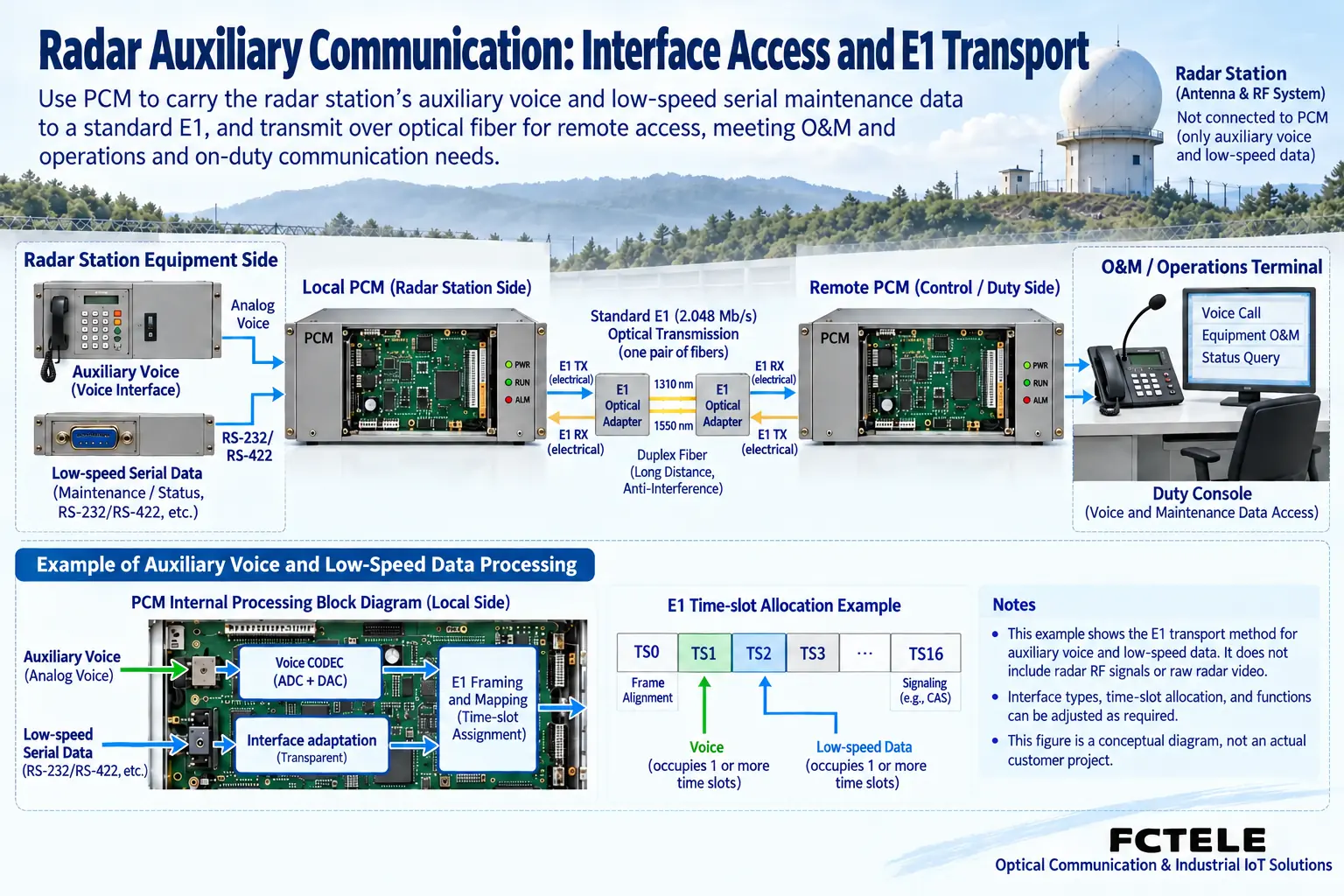
Besides the radar itself, a radar site may also need operator voice, equipment status, and auxiliary control communications. A PCM multiplexer can aggregate and extend the telephone, audio, or low-speed data interfaces it supports; whether it applies depends on the actual service interfaces. It cannot automatically provide transparent transmission of radar RF, raw radar video, or arbitrary high-speed data just because it is installed at a radar site.
Requirements gathering should make the equipment provider clarify the source and output form of each piece of information: is it an analog telephone, four-wire voice, serial bytes, or Ethernet or a dedicated digital interface. Although they may all be called “radar data,” their capacity, latency, and interaction methods can be completely different. This article introduces general methods for auxiliary communication access; it does not correspond to performance measurements of a specific radar project, nor does it constitute a guarantee of compatibility with dedicated radar interfaces.
Determine whether access is possible from service ports
For operator telephones, confirm whether they connect to an ordinary telephone or an existing PBX subscriber port, and check the FXS and FXO roles accordingly. For audio interfaces, confirm the number of wires, input/output direction, level, and impedance requirements; do not assume that because voice exists, any audio line can be connected. When auxiliary equipment outputs serial data, further check the electrical standard such as RS232 or RS485, terminals, rate, parity, and flow control requirements.
The PCM chassis must be equipped with corresponding modules that support these services. Console serial ports are usually used to manage the chassis and are not necessarily user data ports that can be sent to the remote end; the equipment network management port is also not a default radar service Ethernet channel. On site, confirm item by item according to the specific model and board, especially do not infer interface functions only from connector shape. Obtaining manuals and wiring diagrams for both ends is more reliable than first choosing a “radar-specific” name.
How auxiliary services are aggregated into the digital trunk
For analog voice supported by the equipment, the encoding circuit converts it into digital samples, the multiplexing section organizes channels in specified positions, and the opposite end restores the corresponding service. How a serial module maps to the trunk may use different interface adaptation mechanisms, and the corresponding documentation must be checked. Do not treat the 64 kbit/s time slot example for voice as the occupation method for all data modules, and especially do not calculate the number of arbitrary serial ports based on it.
The E1 framing rate is 2.048 Mbit/s, and a common frame has 32 time slots; some positions may be used for synchronization or signaling, so the available service resources are also limited by the specific structure. If auxiliary services exceed the trunk resources, adding access ports will not solve the capacity shortage. The procurement table should list the channels and concurrency conditions required for each type of interface, and then check the bearer capacity against the actual configuration; for high-speed or dedicated interfaces, a transmission solution that meets their requirements should be selected separately.
Distinguish between interface extension and data interpretation
For modules that support transparent serial extension, the goal is usually to deliver the data on the interface to the remote end, not to understand and rewrite the coordinates, status, or command semantics in radar messages. The two end devices must still agree on message format and interaction process. If a system requires converting one protocol to another application protocol, the parsing and mapping capabilities of a dedicated gateway must be confirmed; PCM access equipment cannot automatically be treated as a protocol translator.
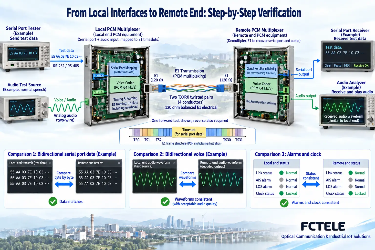
You can use a known auxiliary serial test data segment to verify the received bytes and their order, and then check responses using the real device interaction. Byte consistency is only evidence at the transmission layer; whether the service is correct must also be judged by system status and application process. Similarly, a test tone can help check audio direction, but it cannot replace acceptance of real voice, call signaling, or the audio frequency band required by the service.
Timing and latency requirements must come from the service
Auxiliary voice and control data may have different requirements for continuity and response latency. E1 line timing must be coordinated across the complete network; setting the clock on only one PCM device does not mean the entire link is correct. Among carrier lines, intermediate transmission equipment, and multiplexers at both ends, the clock provision, recovery, and transfer relationships should be clarified, so that there is a basis for locating slips or intermittent anomalies.
If the system specifies an end-to-end response time, it should be measured under actual interface and bearer conditions, not treated as guaranteed by the E1 line rate. Serial encapsulation, module buffering, and intermediate links can all affect latency. Stable clocking also does not mean that all data tasks meet dedicated real-time requirements; for services that do not allow a certain interruption or delay, the system designer must specify test indicators and acceptance conditions.
On-site cabling should isolate incompatible electrical conditions
The electromagnetic environment, outdoor cables, and grounding conditions of a radar site need to be evaluated according to the site design. E1, telephone, and serial interfaces each have corresponding cable and electrical requirements; they must not be subjected to signals or power supply beyond product specifications. Using fiber optic transmission can change the conductive path of the intermediate medium, but the terminals still have power supply and other metal connections, so it cannot be claimed on this basis that the entire system is no longer affected by any interference or surge.
During inspection, record the actual connections between transmission equipment and the shielding and grounding arrangements, and do not arbitrarily change the existing site protection design. Handling involving power, protective grounding, or damaged boards should be performed by qualified personnel according to maintenance procedures. This article does not provide live detection or internal circuit repair steps, nor does it write an unverified surge protection level of a product as a general requirement for radar sites.
Complete joint commissioning in a layered sequence
First check modules, ports, and cables, then verify the E1 signal, frame structure, clock, and alarms; after that, check voice or data channel mapping; finally connect real service equipment for joint commissioning. If the line is synchronized but one channel does not respond, first check the mapping and interface parameters of that channel, rather than immediately adjusting the entire trunk. If all channels are abnormal at the same time, return to checking the shared trunk, power, and clock conditions.
Auxiliary serial tests should save transmitted and received samples and note the interface settings and test direction. Telephone services should test two-way voice, call setup, and release. In concurrent scenarios, run the agreed auxiliary services simultaneously to confirm that there is no miswiring or mutual influence between ports. Test records should state the conditions, and a brief success should not be written as a reliability guarantee under all loads and environments.
Produce delivery documentation with clear interfaces
Suppose a site needs two operator telephones and one status serial port; first draw the interfaces at both ends for these three services, then select PCM modules and a trunk solution that actually support them. This is a requirements organization example and does not mean that a standard chassis provides this configuration by default. If raw radar video has a separate dedicated high-speed channel, it should be marked independently in the diagram to prevent maintenance personnel from mistakenly connecting the two services to the same type of interface.
Delivery documentation should include interface definitions, modules at both ends, channel mapping, trunk and clock relationships, exception handling, and acceptance samples. For product selection, the applicable modules can be checked from Feichang Technology E1 PCM multiplexer documentation, but the final configuration must be jointly confirmed by the supplier and the radar system party. Only by clarifying what the equipment is responsible for transmitting and what it is not responsible for interpreting can auxiliary communication access be prevented from being mistakenly written as a replacement for the entire radar link.
Documentation note: The principle diagrams have been checked for technical content and are used to explain general mechanisms; they are not product photos or measurement records. Specific interfaces, modes, and capabilities are subject to the selected model, version, and on-site verification.
Verification references: ITU-T G.704: Frame structures for digital interfaces
ITU-T G.703: Electrical characteristics of digital interfaces
Feichang Technology E1 PCM multiplexer
Translated from the Chinese technical article. Source first published: 2021-11-12. Source last revised: 2026-10-13T13:23:07+08:00. Read the Chinese source
