


First, the conclusion: Physical isolation and logical isolation both have to answer the question, “Can data from different networks cross over to the other side?” But they do it in different ways. The former emphasizes hardware and channel boundaries; the latter relies on packet handling and access policies inside shared equipment. Fiber is only a transmission medium: using fiber does not mean the network is automatically isolated; several services sharing fiber cannot be considered able to communicate with each other just because of that. To judge a network optical multiplexer or a fiber media converter, you need to look at how ports forward between each other, how bandwidth is allocated, and whether the boundary still holds under management and fault conditions.
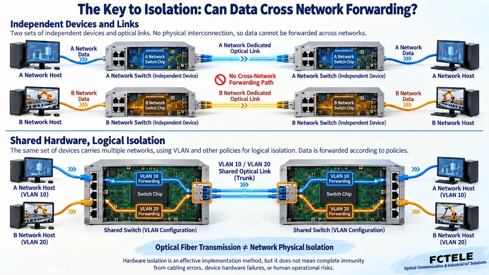
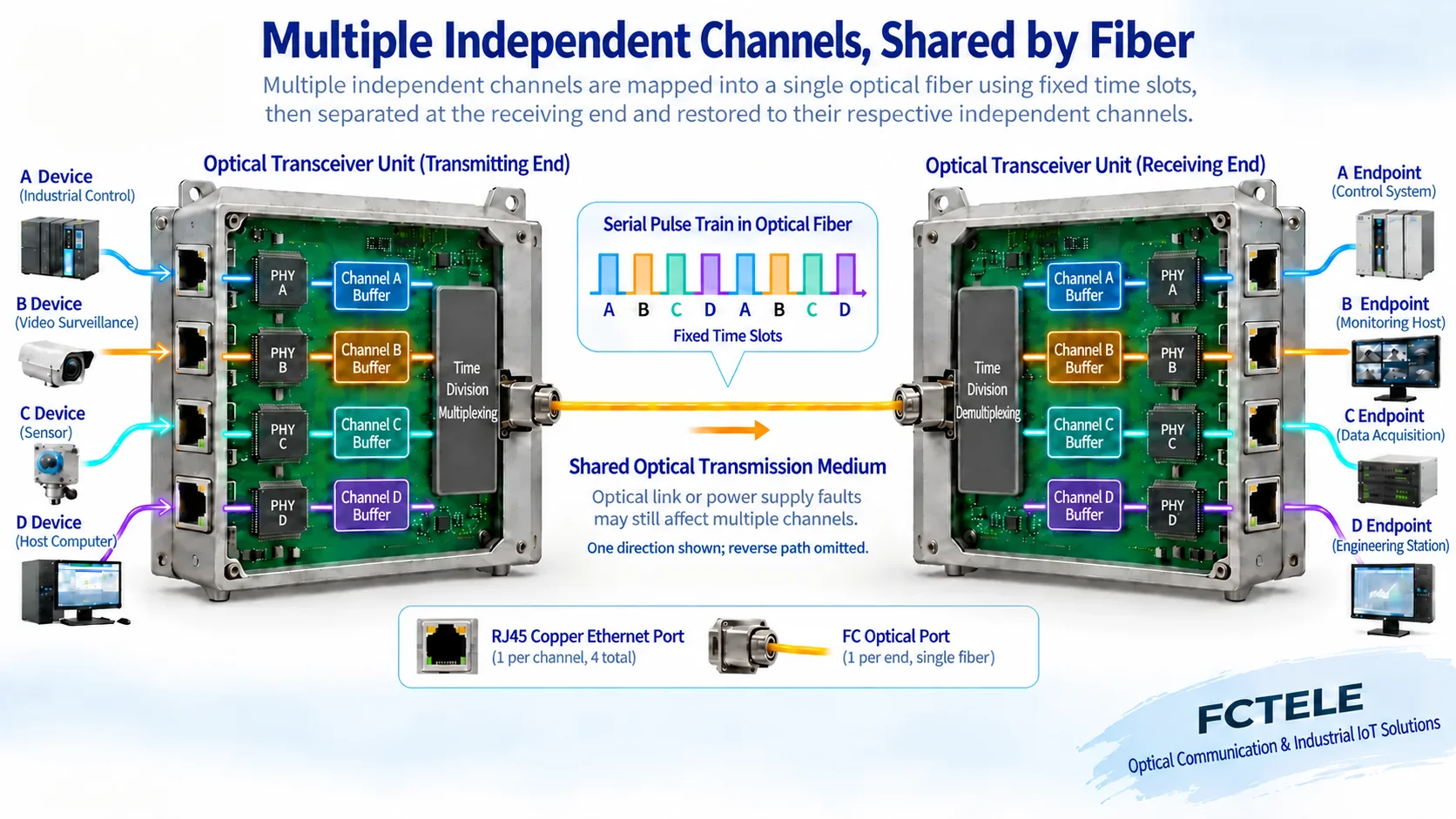
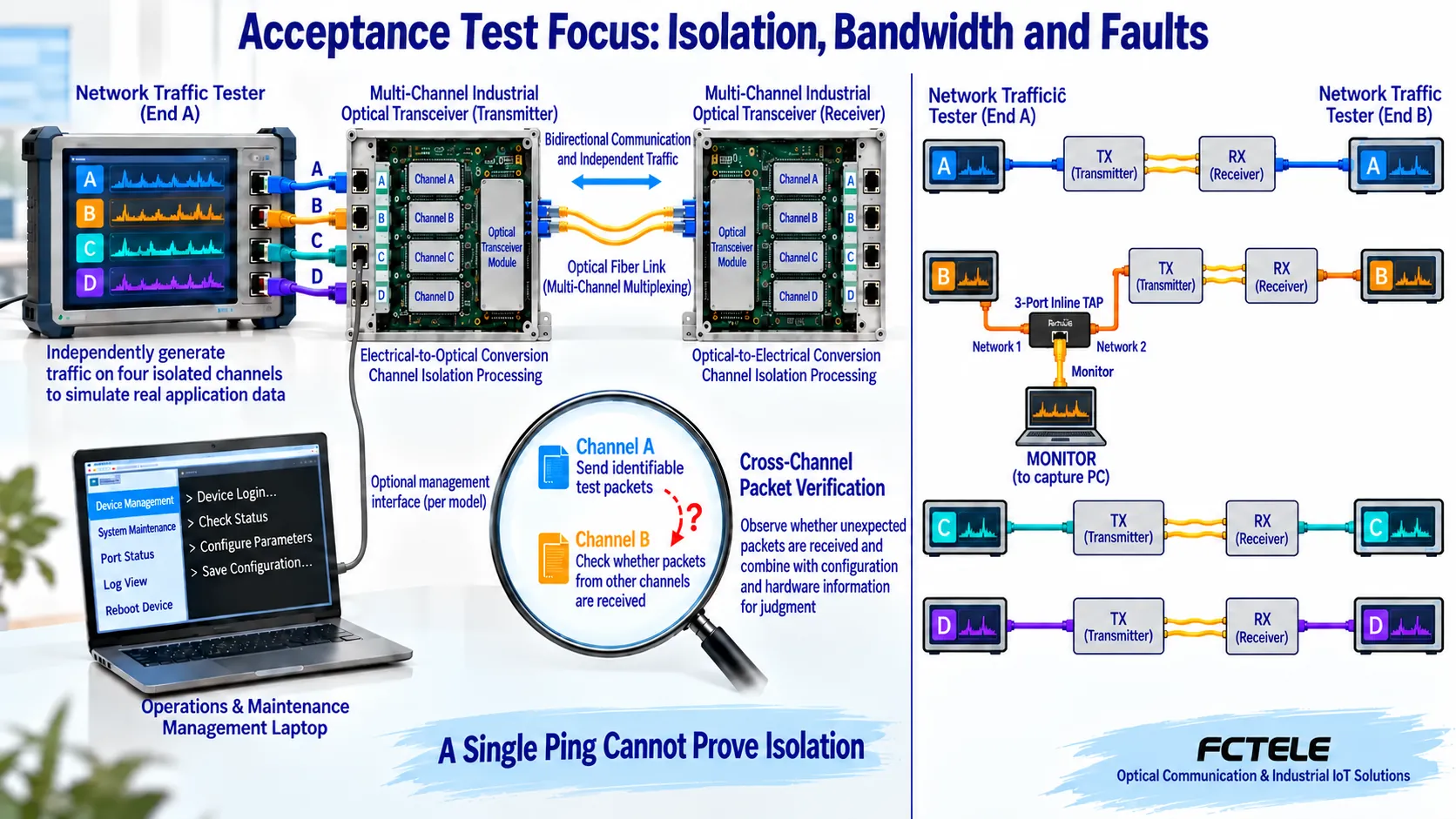
When reading the diagrams, first follow the blue and orange data paths: Figure 1 compares the two architectures, Figure 2 explains how independent channels share optical transmission, and Figure 3 separates isolation, bandwidth, and fault verification. This article focuses on multi-channel Ethernet access and mainly explains how to understand and check product capabilities.
1. First, distinguish: Is it the network that is isolated, or the electrical connection?
Fiber transmits through optical signals, and the two ends of the link do not need to pass data through metal conductors, which helps reduce problems caused by ground potential differences and electromagnetic interference. But the devices at both ends are still exchanging data, so electrical isolation does not mean there is no communication path between the networks. An ordinary fiber media converter usually only converts Ethernet signals between electrical ports and optical ports, and does not automatically become a firewall.
Logical isolation is common in VLANs on shared switches. A VLAN is a virtual local area network, which can be understood as dividing different Layer 2 broadcast domains within the same device: broadcast frames belonging to VLAN 10 will not be sent directly to ports in VLAN 20 according to ordinary Layer 2 forwarding rules. Data frames can be transmitted alternately over the same uplink fiber, and then sent to the corresponding network according to tags. Sharing an uplink does not mean grouping stops working; if there is also a router, Layer 3 switching, or an incorrect bridging configuration, the two networks may still communicate, and access control policies are still needed to restrict them.
Physically separate devices and links are a relatively intuitive isolation architecture. But you also need to check whether there are extra network cables, wireless interfaces, management devices, or other bypasses connecting the two sides. You cannot treat “there are two chips” or “there is no routing function” alone as a complete conclusion, and even less can you promise that configuration, wiring, and operation mistakes will never cross networks.
2. Why can independent service channels still share fiber?
Another type of product is a network optical multiplexer or fiber media converter in which multiple Ethernet channels use independent service channels. It does not necessarily lay one dedicated fiber for each electrical port; instead, it first processes each service separately, then loads them into optical transmission channels according to a fixed correspondence, and restores them to their respective ports at the far end. What is shared is the transmission medium; whether there is a forwardable path between services depends on the internal architecture.
Feichang Technology 1–4 port 100M Ethernet physical isolation fiber media converter public information explains independent FE interfaces and dedicated time-division channels, as well as the design in which four channels each correspond to their own transmission. Time division can be understood as loading each channel’s data in sequence at predetermined positions and separating them at the receiving end according to the same rules; this is a different way of organizing services from an Ethernet switch performing statistical multiplexing of data frames on a shared uplink. Figure 2 only explains this difference and does not represent the actual chip layout, time slot length, or private protocol details of any model.
The road analogy is still helpful: a shared uplink is like several traffic streams entering the same road, while independent channels are like reserving separate passage shares for each stream. But there are no four visible “lanes” in the fiber, and the analogy cannot be used to prove security. Independent interface chips are part of the architecture, and port mapping, internal forwarding capability, and management boundaries still need to be checked.
Take four 100M channels sharing one 100M uplink as an example. In this case, concurrent traffic may indeed contend for uplink capacity; but not all VLAN devices have only a 100M uplink. Conversely, the independent service capability of four 100M channels cannot directly lead to the conclusion that the physical optical line rate is exactly 400M, because transmission may also include encoding and protocol overhead. Selection should compare the service capacity of specific devices, not just compare the two names “physical” or “logical”.
3. How do you check isolation, bandwidth, and fault boundaries?
First list the communication relationships. For example, A can only reach remote A, and B can only reach remote B; if some services are allowed to cross domains, write down the allowed direction, protocol, and ports. Then confirm the electrical port numbers at both ends, the corresponding channels, rate, duplex, optical port specifications, and management access method. The independent channel capability given in official website product information needs to be tied to the actual ordered model and delivered configuration, and cannot be generalized to mean that all Feichang Technology media converters have the same function.
Step 1: Verify the corresponding channels. In an independent test environment, connect test devices channel by channel and confirm communication relationships such as A to A and B to B. Then send identifiable test traffic from one channel and check whether data frames that should not arrive appear on other channels. You should look at both the actual service direction and the handling of broadcasts and different destination addresses; a failed ping to one address may simply be due to a firewall, address, or wiring reason, and cannot by itself prove isolation.
Step 2: Verify concurrent bandwidth. After testing a single channel, make all channels work at the same time and record the throughput, packet loss, and latency changes of each channel. The test scope should include frame length, direction, load, and test duration. A port showing a negotiated rate of 100M, or a ping latency that does not change once, does not mean that the channel retains independent service capacity under concurrent load. Bidirectional capability also needs to be checked separately in both directions.
Step 3: Check management and faults. Check the management account, the network allowed to access the management interface, configuration permissions, and port mapping after restart, optical path interruption, and recovery. Different services not forwarding to each other does not mean that a shared fiber break or a whole-device power loss affects only one channel. When higher availability is required, optical path backup, power supply, and device faults should be evaluated separately; “independent bandwidth” cannot replace redundancy design.
Observing a port loopback can at most help discover certain switching behaviors, and cannot serve as sufficient evidence for determining isolation. Do not directly connect two ports with a network cable to form a loop in a running service network; if special fault testing is needed, follow the device manual and prepare current limiting, recording, and recovery measures in an independent laboratory environment.
4. Several easily confused questions
Does VLAN isolation have no effect?
No. VLANs can divide Layer 2 broadcast domains, and with correct routing and access control, they can achieve clear logical boundaries. Their dependency conditions differ from those of independent hardware channels, and selection should be based on project requirements; you cannot simply say that data in shared fiber is “mixed together and therefore completely unisolated.”
Does independent bandwidth mean the entire system is completely independent?
No. Service channels can each retain capacity, but the chassis, power supply, optical path, or management facilities may still be shared. Service isolation, capacity assurance, and fault isolation need to be checked separately.
Can a fiber media converter replace a firewall or dedicated isolation device?
An ordinary media converter mainly converts the transmission medium and does not automatically provide access filtering or content inspection. If a project explicitly requires a specific security boundary, the complete architecture, product implementation, and applicable requirements should be checked, and the decision should not be made based only on the name “physical isolation.”
5. Do not describe service isolation as encryption or one-way security isolation
Independent service channels limit the internal forwarding relationship between different services, and do not automatically encrypt normally transmitted data. Fiber can reduce conductive paths across sites, but it cannot check sender identity, prevent authorized terminals from issuing incorrect commands, or replace message authentication. CRC is a check used to detect transmission errors and cannot be used as a basis for tamper prevention or access authorization. These functions need to be clearly assigned to specific devices in the complete architecture.
A bidirectional optical multiplexer still allows corresponding ports to exchange data in both directions, and because its name contains physical isolation, it cannot be called a one-way transmission device, an air-gapped system, or a device that has obtained a certain security certification. If a project requires a strict security boundary, the specific product implementation, management entry points, external bridging, and applicable requirements should be checked. NIST’s OT security guide emphasizes zoning and controlled communication, which needs to be designed together with site risks, allowed services, and maintenance methods.
Electrical isolation can help deal with ground potential differences; independent service channels can help maintain each channel’s mapping; shared chassis and optical cables may still fail at the same time. The acceptance report should separate these conclusions and record test direction, load, version, packet capture, and recovery behavior. A failed ping, normal port lights, or no broadcast storm cannot independently prove that the system is completely isolated.
Information note: The first three figures are general principle illustrations, not actual products, internal circuits, or measured data of specific models. The capacity, channels, and chip layout in the figures do not represent the specifications of the entire series; specific capabilities are subject to the delivery materials of the selected model. Verification materials: Feichang Technology physical isolation media converter category, 1–4 port 100M product information, Cisco inter-VLAN routing explanation, NIST OT security guide.
Translated from the Chinese technical article. Source first published: 2019-10-14. Source last revised: 2026-10-13T13:42:26+08:00. Read the Chinese source
