


The value of management is making problems observable
A managed PoE switch both handles Ethernet data and controls power supply to the relevant ports, and it also provides a channel for configuration and status observation. It suits scenarios where multiple cameras and APs are deployed in a distributed way and faults need to be identified from a distance. The management page opening only shows that part of the management path is reachable; it cannot be used to conclude that all camera power supplies and all data outlets are normal.
When selecting a model, first write down the questions you need to answer: which terminal went offline, whether it restarted, which port refused to supply power, whether the outlet is congested, and whether the input power has any abnormality. Then confirm which fields and recording methods the candidate model provides. Do not understand “managed” as automatically fixing all faults, and do not infer from another brand’s manual that Feichang Technology products have exactly the same menus.
What the three paths inside the chassis each do
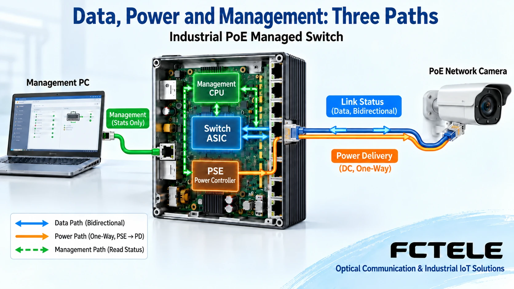
Data enters the interface circuit from the network port, and is then sent by the switching chip to the corresponding outlet according to forwarding conditions. The PoE controller is responsible for powered device detection, allocation, monitoring, and applicable protection. The management processor reads the status that can be provided and accepts configuration requests. The three work together, but network access permission, whether the terminal draws power, and service forwarding are not the same status.
Therefore, logging in to the management address with a browser cannot add a power-receiving circuit to an incompatible terminal; changing the IP will not increase the overall power budget either. If a camera’s service does not work, it may be an address or VLAN problem, or it may be that power has not arrived or it is repeatedly restarting. First propose hypotheses along the functional paths, then check the corresponding status; this makes it easier to find evidence than changing all parameters at once.
Several wattage values on the PoE page cannot be read interchangeably
Port capability, the amount already allocated, the current actual consumption, and the remaining overall budget each answer different questions. A port currently having only eight watts does not mean the system must reserve only eight watts for it; classification, negotiation, or configuration may determine another allocated amount. Whether a new terminal can be connected must be judged according to the specific device’s rules and maximum demand.
Status names also vary by platform, for example no PD detected, insufficient budget, power being supplied, overload, or temperature protection; they cannot all be uniformly interpreted as a bad network cable. On first use, refer to the local manual to confirm the measurement location, unit, and refresh cycle of the fields. The absence of a certain telemetry item does not mean the related abnormality does not exist; other suitable records or tools are needed to supplement it.
A normal data link may still have abnormal service
Physical link status indicates that the port has established the corresponding connection, while the actual negotiated rate helps identify whether the link is working at the expected rate. Error counters, discard counters, and outlet utilization can provide different clues: receive errors may involve physical signals, and outlet discards may involve queuing and capacity, but the counter definitions still need to be checked; not all packet loss can be attributed to power supply.
VLAN is used to divide the Layer 2 forwarding scope; a management VLAN may also prevent the operations computer from accessing the device. It is not data encryption, and it cannot replace access control and correct network design. Before changing the VLAN or uplink method, keep a configuration backup and confirm the path for continuing to manage the device, so that a single remote operation does not cut yourself off from the device.
How to relate evidence when a camera goes offline at night
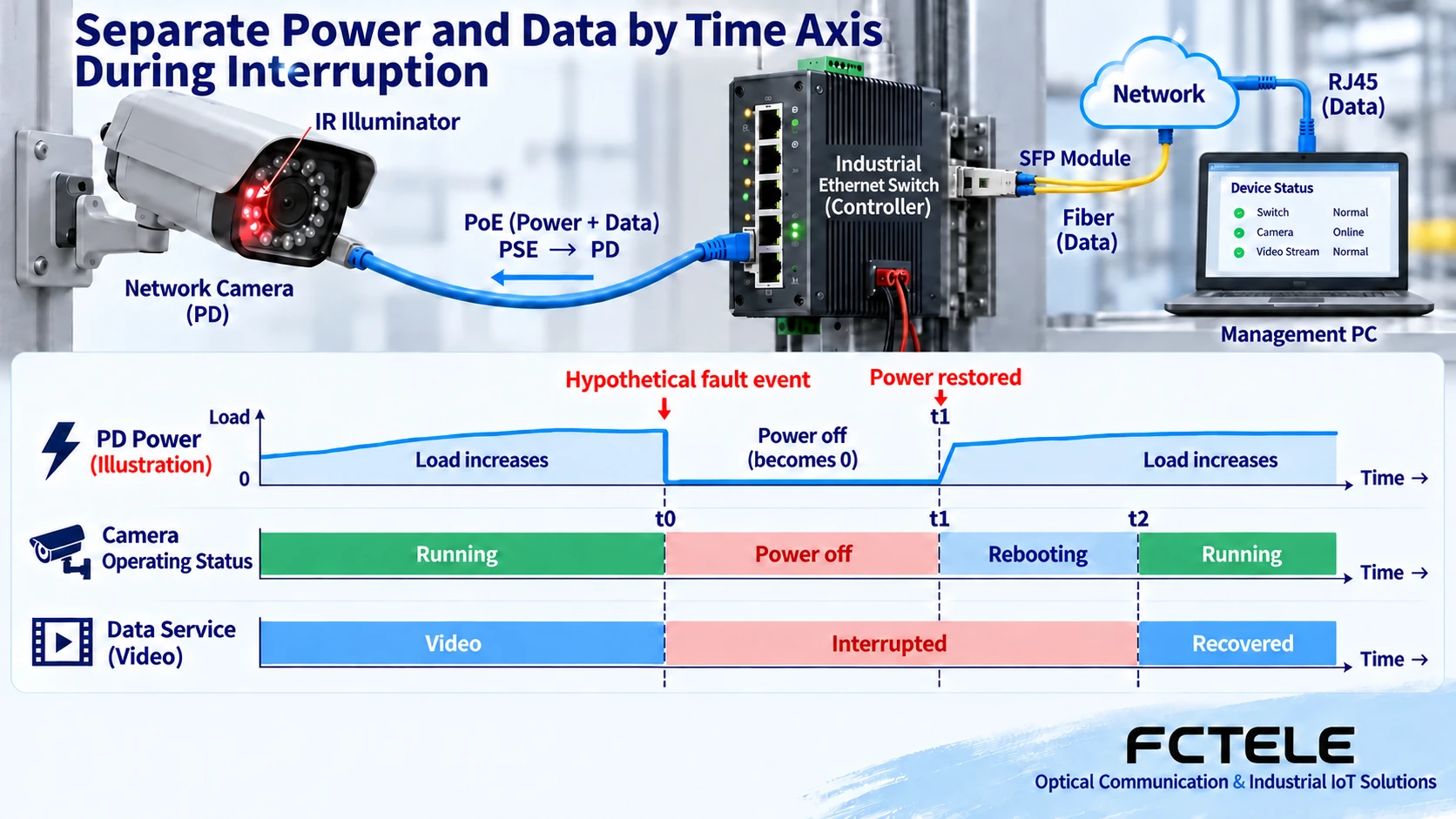
Assume it is normal during the day, and a certain camera loses its stream at night after the fill light turns on. First put the recording event, terminal uptime, PoE status, link changes, and input power records on the same timeline. If the terminal uptime resets and a power supply shutdown record appears at the same time, check along power and cabling first; if the terminal keeps running while outlet discards increase, check conditions such as network load.
Inconsistent device clocks will distort the order of events, and log overwriting or polling intervals may also miss brief changes. When time synchronization and remote logging can be provided, configure them according to the actual supported capabilities; when the corresponding functions are not available, use external records that can be reviewed. Correlation shows which phenomena occurred at the same time, but a comparative test is still needed to confirm the cause; do not assert causation just because they appeared at the same time.
Why remote power-off restart must be controlled
Turning off a PoE port will cause the powered terminal to lose energy, which may affect recording, access control, or ongoing services. This is not the same operation as only disabling the data port, and the specific device may also link the two. Before execution, check the terminal corresponding to the port, the scope of impact, the maintenance window, and the recovery path; do not treat the web button as a cleanup function with no impact.
Successful recovery after a restart is only a phenomenon; it cannot prove that the root cause has been solved. If poor line contact or insufficient budget still exists, the fault may appear again. First keep the logs and current status, then under approved conditions perform one documented restart; multiple automatic power cycles may also hide the problem, so the strategy should be designed and verified according to the actual service.
Priority cannot create extra power capacity
Some platforms support preferentially retaining specified ports when power is insufficient; this only determines how the limited amount is allocated, does not increase total capability, and does not guarantee that all cameras continue running. Priority, maximum allocation, and power-refusal policies should be confirmed against the local device, to avoid critical equipment and general equipment both being in unclear default behavior.
The Feichang Technology 3243 details list directions such as management, VLAN, optical-electrical combinations, and PoE options, and are suitable for first planning on-site access and uplink. Whether specific port power telemetry, alarm fields, scheduled power supply, and remote restart are provided still needs to be checked with the manufacturer for the delivered version and firmware; this article cites Cisco materials to explain management concepts, and this is not proof that Feichang Technology has the same commands or functions.
Industrial installation and redundancy must also be verified separately
Input power, terminals, cabinet temperature, and heat dissipation affect overall operation, and after the PoE output load increases, it needs to be recalculated. A fiber uplink only transmits communication data, and the remote end still needs local power. Dual power input must be checked for capacity and input switching behavior when one path fails; having two sets of terminals in the chassis does not mean there is no common failure point in the entire site.
Ring network protocols are responsible for the data backup path, and ports and topology usually still need to be set according to the design. Do not randomly form all interfaces into a loop and expect the device to operate safely automatically. When input power fails, the PD at the powered-down node may restart even if other nodes can still communicate; power continuity and network recovery should each have acceptance records.
After establishing a baseline, change one condition at a time
First use a compliant short cable and a known compatible PD to establish a baseline, and record power supply, link, and actual service. Then gradually switch back to the original cable, original port, and production load, and compare whether the problem follows the cable, port, or terminal. Do not simultaneously change the power supply, change the VLAN, and restore factory settings; otherwise, even if it improves, it is hard to tell which step was effective.
Delivery materials should include a port-to-terminal mapping table, power supply standard, budget, management address, and configuration backup, and should also explain log retention and fault operation procedures. When terminals are added later, recheck both power supply and uplink capacity. The premise for management functions to truly help maintenance is that fields have clear meanings, events have time records, and operations have verifiable results.
Documentation note: The principle diagrams have been checked against technical content and are used to explain general mechanisms; they are not product photos or actual measurement records. Specific interfaces, modes, and capabilities are subject to the selected model, version, and on-site verification.
Verification materials: Cisco industrial switch PoE management materials
TI PoE interface and powered device conversion materials
Feichang Technology 4-copper-port, 2-fiber-port managed industrial switch and PoE option
Translated from the Chinese technical article. Source first published: 2020-01-10. Source last revised: 2026-10-13T13:42:26+08:00. Read the Chinese source
