


Professional audio fiber connections need matching input levels, channel directions and end-to-end delay. Fiber can replace the long span between stage and mixing position, but it does not mix audio or drive loudspeakers. Direct microphone connection depends on appropriate input gain and power. Performer monitoring requires measurement of the entire return chain.
Separate microphone, line and speaker-power signals
A microphone normally supplies a weak audio signal needing a preamp. A mixer’s line output uses another level range. A power amplifier output drives a speaker and must not feed an ordinary optical audio input. All carry sound but have different interface conditions. A microphone into a line input may be too quiet; a strong output into a low-level input can overload or damage it.
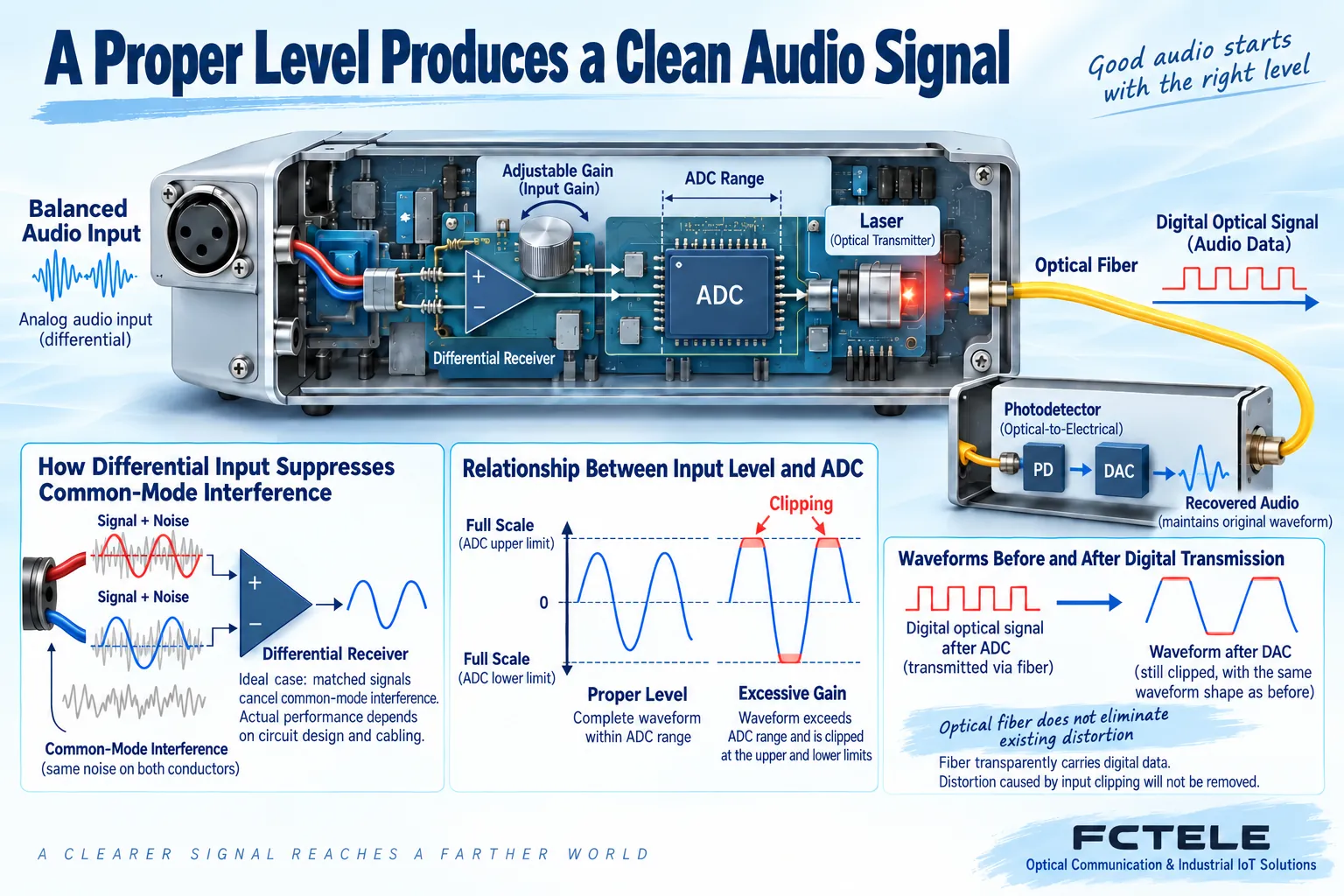
An ADC reads analog voltage into numbers within an allowed range. Gain brings a weak source into a suitable range; more is not always better. Too little gain followed by downstream volume increase also amplifies front-end noise. Too much exceeds conversion range and flattens peaks: clipping. That happens before fiber, so stable optical transport cannot reconstruct the lost peaks.
XLR is a connector shape, not a signal specification
Balanced audio carries differential information on two conductors. A suitable receiver reads their difference and can reject interference coupled similarly into both, subject to wiring, impedance balance and circuit limits. It does not remove every noise source. Shield connections and protective grounding serve different purposes; do not disconnect protective earth to eliminate hum.
XLR may carry balanced analog audio or AES/EBU digital audio. Matching plugs do not make their protocols and electrical requirements interchangeable. RCA commonly serves unbalanced signals. Adapters change connections, not automatically preamp gain, impedance and signal format. Check manuals before deciding on preamps or dedicated conversion.
Phantom power feeds suitable microphones through an appropriate microphone input; an ordinary line input does not supply it by default. FCTEL’s FCA-A8-H product page explicitly lists XLR and input phantom power. That supports evaluation for microphones requiring it, while microphone type, gain and ordered configuration still need checks. Do not generalize this feature to other audio fiber products.
Draw uplink and return separately
Suppose four stage signals travel to a control room and two monitor feeds return. Sources or preamp outputs enter stage transmit channels, pass through fiber, and leave control-room receivers for mixer inputs. The return runs from mixer outputs to control-room transmit channels, then stage receivers and monitor amplifiers or powered monitors. A receiver output connected to a mixer output joins two outputs rather than create a valid signal path.
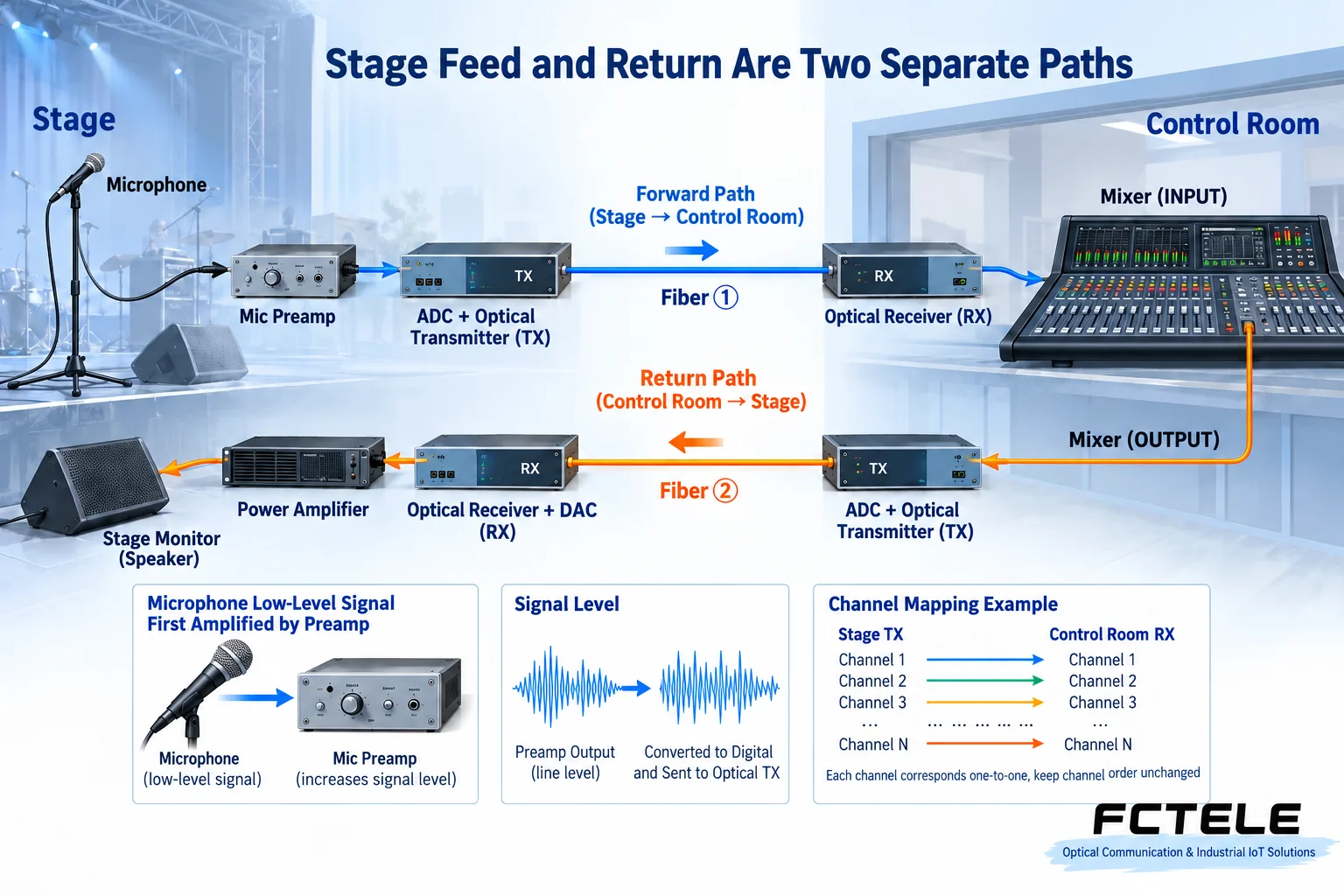
For stereo, account for left and right channels separately. Eight channels may mean eight mono signals or another grouping; eight one-way versus four bidirectional channels also needs confirmation. Number and label ports and cables, then test one signal at a time to find cross-connections and stereo swaps rather than connect everything and guess.
Perceived delay is not only fiber propagation
Preamps, sampling, packaging, transmission, reception and conversion all take time. Digital mixer effects, wireless microphones and monitoring processors can add more. Propagation in fiber is only one component. A converter advertised as low latency does not establish that a performer’s voice-to-ear chain meets requirements, and is not zero latency.
Use a synchronized test event or suitable audio measurement equipment to compare source and final output timing. Include the processors actually used and record mode, channel and sampling configuration. Sound reinforcement also involves distance-dependent acoustic propagation from speakers. Equipment delay and arrival time at an audience position are different; an optical converter does not solve room acoustics automatically.
Check cable, environment and faults beyond promotional claims
Permanent theaters can use installed cable suited to the route. Temporary events especially need clean connectors, protected cable, appropriate bends and protection from foot traffic. The glass span reduces long-copper coupling, but supplies and analog I/O can still introduce noise. Outdoor, damp and high-temperature suitability follow model ratings; professional audio wording is not a weatherproofing classification.
Before the installed route, confirm matched optical endpoints, fiber mode, wavelengths and transport protocol, then measure received power. Short-link tests still need overload checks; choose attenuation according to specifications. Never look into a laser port or wipe end faces with fingers. For applications and power-budget sequence, see Audio fiber applications and boundaries.
Deliver reproducible sound checks
Lower amplifiers and monitoring volume first. With known sources inside the input range, verify sound, direction and stereo correspondence one channel at a time. Check noise, maximum normal level, frequency response and distortion according to requirements. Quantitative acceptance needs appropriate instruments rather than phone recordings. Measure the actual return chain and assess mute/recovery behavior.
For silence, check input mode, mapping and mixer mute. For distortion, inspect front-end level and receiver/downstream matching. For hum, isolate source, supply and analog cable segments rather than assume fiber is responsible. Document connectors, phantom-power state, gain, channel maps and measurements for future replacement or expansion.
Reference note: the documented FCTEL model supplies the stated input features; actual power and interfaces follow its manual. For gain and ADC principles, see TI audio ADC documentation, without implying use of that chip in FCTEL equipment. Figures illustrate generic mechanisms, not product teardowns or measurements.
Translated from the Chinese technical article. Source first published: 2024-05-08. Source last revised: 2026-10-13T14:22:45+08:00. Read the Chinese source
