


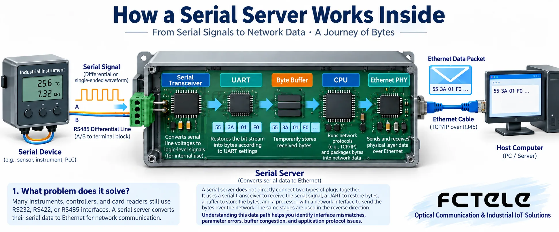
A serial server does not directly connect two types of plugs together. It first uses electrical transceiver circuits to receive serial signals, restores bytes through a UART, and then sends the bytes into the network through a processor and network interface. The reverse process also goes through these stages. Understanding the internal data path is necessary to distinguish wrong interface connections, mismatched parameters, buffer congestion, and application protocol errors.
1. What problem does it solve?
Many instruments, controllers, and card readers still use RS232, RS422, or RS485 interfaces, while computers and central systems mainly use Ethernet. A serial server moves data between the two, allowing existing terminals to be accessed through the network. It does not understand measurement values just because a network cable is connected, nor does it guarantee that all old software is fully compatible, and it does not make device processing speed infinitely faster.
Suppose a computer needs to read an instrument. The computer first establishes the specified network channel and sends a request that the instrument can recognize; the serial server sends the request bytes to the instrument, then passes the reply back to the computer. Which field in the request is the station number and which field is the reading is defined by the application protocol. Transparent transmission and protocol conversion are different capabilities and must be confirmed separately when selecting a model.
2. What do the electrical transceiver and UART each do?
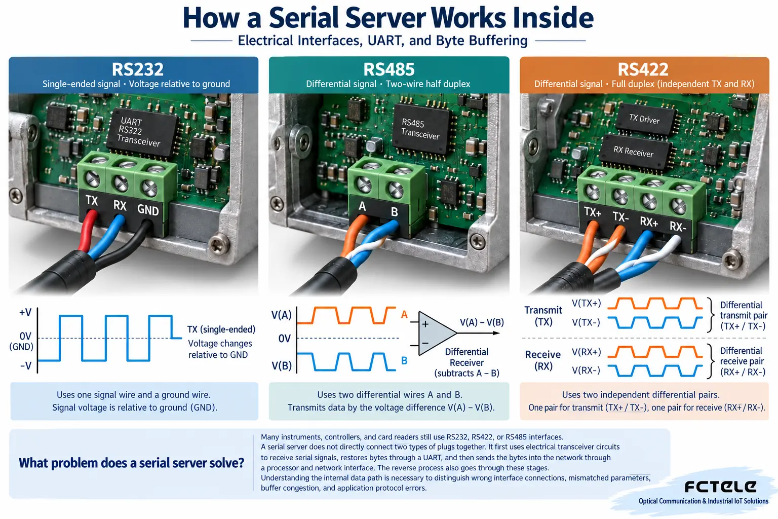
What first appears on the cable is an electrical signal, not an already interpreted register value. The serial electrical transceiver is responsible for the level and drive of the corresponding interface. RS232 is commonly a signal relative to a reference point, RS485 uses the voltage difference between two signal lines, and RS422 usually uses independent transmit and receive differential pairs. They cannot be directly interconnected just because their terminals look similar.
The UART is an asynchronous serial controller responsible for transmitting and receiving according to the agreed byte format. When transmitting, it organizes the data into a start bit, data bits, an optional parity bit, and stop bits; when receiving, it judges the signal according to the baud rate and format and restores the bytes. The baud rate, data bits, parity bit, and stop bits must all match; you cannot check only that “both are 9600.”
Older articles describe Modbus as a required “communication chip,” which is misleading. Modbus is a communication protocol, and its messages can be parsed by software on the processor; the device does not need to have a specially named Modbus chip. Likewise, having an RS485 interface only indicates the electrical connection method and does not prove that the device can convert Modbus RTU to Modbus TCP.
3. Why buffers cannot be omitted
Serial and network data do not arrive at the same pace. Ethernet may deliver many bytes at once, while the serial port needs to send them one by one at the baud rate, so the device needs buffering for temporary storage. When receiving in the reverse direction, serial bytes may also accumulate to a certain length or wait for a certain interval before being handed to the network for transmission.
A buffer is like a temporary staging area, but its capacity is limited. When the network continuously writes faster than the serial port can output over the long term, the queue may keep growing until flow control, rejection, or dropping is triggered; the specific behavior depends on the model. A high network interface rate does not mean the terminal serial port can be equally fast. For continuous transmission, check flow control, application acknowledgments, and device buffering rules.
TCP provides an ordered byte stream and maintains byte order during normal delivery, but it does not preserve the message boundaries of each application write. The application must still accumulate bytes and frame them according to its own protocol. Even if the buffer has not overflowed, treating a half frame as a complete frame will cause parsing failure, and not all problems can be attributed to hardware packet loss.
4. Processor, network interface, and management functions
The processor runs configuration and network communication programs and manages serial channels, connection status, and buffering. The Ethernet interface performs the corresponding network signal transmission and reception; RJ45 is only a common electrical port connector, and the plug shape alone cannot determine the speed, power supply, or service protocol supported by the device. Products with optical ports also require checking the optical module and link specifications.
Management web pages and service data channels must also be distinguished. An HTTP web page is used for configuration, but it does not mean instrument data must be transmitted over HTTP; only when the device supports TCP Client, TCP Server, or UDP does it indicate the corresponding service access modes. Available modes, concurrent connection counts, keepalive, reconnection, and registration functions should be checked against the actual model and firmware.
A watchdog is an abnormality monitoring and reset mechanism that can be used to restore operation when a program stops responding normally. However, a reset will not fix incorrect wiring, station number conflicts, or inappropriate application timeouts, nor can it prove that control commands have not been executed repeatedly. If a device frequently restarts, record the cause rather than treating automatic restart as normal stable operation.
5. Isolation and protection cannot be judged by chip names alone
Isolation is used to limit direct conductive paths between different electrical parts, while surge protection is used to handle transient impacts under specified conditions; the two are not the same function. Independently numbered serial ports also do not mean there is electrical isolation between channels. It is necessary to determine whether isolation is between the serial port and the system or between ports, as well as the rated conditions and grounding requirements.
Industrial sites should also check power input, enclosure installation, and environmental requirements. The words “industrial grade” cannot be used to infer that all products have the same lightning protection level or temperature range. During maintenance, do not open the cover and short unknown terminals yourself; loopback testing must use the method permitted by the corresponding interface, and in particular, do not apply RS232 test wiring to an RS485 bus.
6. Locating problems along the internal path
When the network connection fails, first check the address, port, role, and access policy; when the network connection succeeds but there is no serial response, check whether the request reaches the serial output, then verify the interface, wiring, format, and instrument station number. If reply bytes are seen but the reading is wrong, keep the raw message and check the parsing rules, scaling, and byte order.
For testing, first use a short cable and one known-good terminal, change only one condition at a time, and record the counts on both the serial and network sides. Then gradually increase the load and check continuous operation and disconnection recovery. For control services, also verify the command state after a timeout, and avoid treating retransmission as a universal solution for all faults.
7. Confirm capabilities with specific products
The Feichang Technology FCT-1500 series details list RS232/422/485 interface configurations, virtual serial port, and TCP Server/Client modes, and can serve as a reference for selecting models to network distributed terminals. The optical port configurations provided by the corresponding series can be used for remote network transmission, but the serial type and protocol conversion capability still need to be confirmed according to the ordered model and enabled mode.
When selecting a model, first list the number of interfaces, electrical standards, application protocol, and software access method, then consider management and diagnostic functions. Retaining existing terminals can reduce modification work, but compatibility testing cannot be omitted. Separating hardware, electrical format, and service protocol helps beginners understand why “can connect,” “can receive bytes,” and “service is correct” are three different judgments.
References:IETF TCP specification;Feichang Technology FCT-1500 series details. The illustrations are generic principle diagrams and do not represent actual products or measured results.
Translated from the Chinese technical article. Source first published: 2022-04-26. Source last revised: 2026-10-13T20:24:48+08:00. Read the Chinese source
