


Whether to choose a 100 Mbps or 1000 Mbps surveillance network should be based on calculating the bitrate actually passing through each link, especially the uplink shared by multiple cameras. You cannot use a fixed number of cameras based on pixel count, nor treat “100 Mbps can only use 50 Mb/s” as a rule for all switches. First list the bitrates and access paths, then leave reasonable margin, and finally verify with real business traffic.
Cameras generate bitrate, switches forward packets
A camera encodes images into continuous video data, and the bitrate indicates how many bits are generated per second. A switch usually does not recompress video; instead, it forwards Ethernet packets that carry this data. Therefore, so-called “calculating switch bitrate” is actually estimating the business traffic passing through a certain port and whether that egress can send it in time. Recording storage requirements are related to network link requirements but are not exactly the same; you cannot directly treat the recording file size as the traffic on all links.
Network engineering commonly uses decimal units: 1000 kb/s equals 1 Mb/s; to convert Mb/s to MB/s, divide by eight. Do not mix kilobits and kilobytes, and do not uniformly convert by 1024 without explanation. Statistics interfaces may use different display methods, so you should verify the units and sampling period. When reading the same data from different tools, first confirm whether they are counting valid video, protocol packets, or total port traffic.
Only add services that pass through the link being calculated
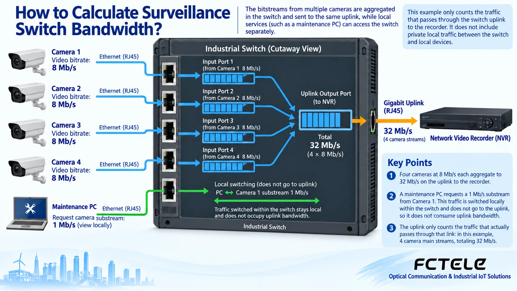
Assume four cameras each have one 8 Mb/s main stream sent to the recorder. Their shared uplink must carry at least about 32 Mb/s of video data, plus audio, protocols, and other services passing through that link. This is a teaching example, not a bitrate that any pixel count necessarily corresponds to. A single camera’s access port only carries its own traffic, while the uplink shared by four cameras carries the aggregated traffic; the same camera-count conclusion cannot be used for both.
Main streams and sub-streams should not be mechanically added together under all circumstances. Only streams that are actually requested and pass through this link should be counted. If a maintenance computer and a camera are on the same access switch, the sub-stream being viewed may be forwarded locally and not pass through the recorder uplink; if the client is on the other side of the uplink, it needs to be counted. Multiple clients each requesting unicast video may also produce multiple transmissions of the same content. Whether multicast can reduce duplicate transmission on a certain segment depends on the devices and network configuration, and you cannot assume it is already enabled.
Average bitrate and peak bitrate need to be recorded separately
The amount of video data is affected by encoding method, image complexity, motion, noise, frame rate, and quality settings. Two cameras with the same resolution may not have the same bitrate; the same device may also vary between a quiet scene and a scene with many people moving. H.265 may improve compression efficiency, but it cannot be promised that it will save exactly half compared with H.264 in any scenario. You should first read the camera’s bitrate control documentation, then observe with scenes that match the site conditions.
Variable bitrate allows the data amount to change with the picture; maximum bitrate or average bitrate control has its own trade-offs between quality and time scale, and the specific behavior should be checked against the camera implementation. Planning only with a one-minute average may miss short-term peaks. Recording should also cover nighttime, complex motion, event recording, and multi-person preview states, to confirm that the statistics period does not smooth out key bursts. Do not trade unlimited bitrate reduction for superficially acceptable traffic while making the recording quality useless.
Why does it still stutter or drop frames when there is margin?
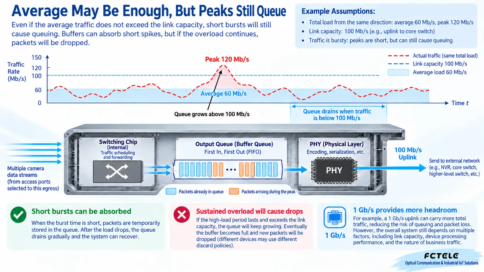
The egress can only send at the link rate at each moment. When the ingress suddenly sends more packets, the switch temporarily stores the data not yet sent; after the burst ends, the freed sending capacity gradually shortens the queue. If traffic continuously exceeds the egress capacity, the buffer will eventually be exhausted, and packets may then be dropped. Buffering does not increase line rate, and QoS priority does not create bandwidth out of thin air; it only determines the processing order of different services during congestion.
A 100 Mb/s port does not have a fixed limit of only 50% or 70% usable. The effective business ratio is affected by packet size, protocol overhead, device performance, and test method. Planning margin is an engineering choice, and you cannot falsely claim that the hardware is inherently halved. First measure actual traffic and errors, then determine the allowed sustained utilization and burst space; for critical control or surveillance services, the margin should match the service reliability target, and you cannot apply a universal percentage.
Build a capacity budget segment by segment from access to recorder
First draw the connections among cameras, access switches, aggregation devices, recorders, and clients, and mark the direction and service source of each physical link. For each egress, add the concurrent bitrates passing through that point, include audio, management, and other shared services, then consider protocol overhead, peaks, and expansion. A full-duplex link has independent sending capacity in both directions, so you cannot simply divide the requirement in one direction by two; when playback and upload coexist, you must also confirm their respective flow directions.
The Feichang Technology DIN-rail switch catalog provides different optical and electrical port combinations, and during selection you can check the access ports and uplink separately. Its 10-gigabit 4-optical 8-electrical product details clearly distinguish optical port and electrical port capabilities; high-speed aggregation can provide capacity for multiple access traffic, but this does not prove that any number of cameras can run simultaneously. Optical module and link compatibility, overall forwarding, recorder network ports, storage write performance, and decoding capability should all be checked together, to avoid upgrading only the switch while leaving other bottlenecks in place.
Use business testing to decide the final configuration
During acceptance, first check whether the ports negotiate to the planned rate, then simultaneously enable the planned recording, real-time preview, event services, and playback, and observe sustained traffic, short-term peaks, errors, and packet loss. If network transmission is normal but the picture still stutters, further check the recorder’s disk writing, CPU, decoding, and the camera itself, and do not attribute all problems to the switch. Tests should use the same image quality and concurrency conditions to compare the effects before and after the upgrade.
Keep each camera’s encoding parameters, number of requested streams, topology, port counts, and recording results to form a traceable capacity table. Recalculate after adding terminals or changing client access methods. Stress testing should be conducted on an isolated test network or during an approved maintenance window, with configuration backed up in advance and a rollback plan arranged; do not use production video services for unplanned experiments. A qualified capacity plan should be able to explain why each link is sufficient, rather than just reporting a single number of “maximum how many cameras can be connected.”
Mechanism reference:Axis bitrate control documentation; product basis:Feichang Technology DIN-rail switch catalog, 10-gigabit 4-optical 8-electrical details. The schematic diagrams are general mechanism illustrations and do not represent actual measurements of specific products.
Translated from the Chinese technical article. Source first published: 2020-06-03. Source last revised: 2026-10-13T20:37:04+08:00. Read the Chinese source
