


The role of a serial server is to connect instruments, controllers, and other devices that originally could only communicate through a serial port to a network. Using it correctly is not just filling in an IP address: first confirm the serial interface and protocol, then complete wiring, serial parameters, network role, and host software settings, and finally verify that requests and responses travel completely round trip. Below, starting from a short-link test with one device, we explain clearly why each step is done.
1. How It Connects Serial Devices to a Network
A serial port sends bits one after another along a wire, and the receiving end restores them into bytes according to the agreed speed and format. Inside the serial server, the transmit and receive circuits first handle the electrical signals, then the UART (Universal Asynchronous Receiver/Transmitter) receives bytes, and after the bytes are buffered they are sent to the network. In the reverse direction, bytes received from the network are queued and sent through the UART and serial circuit to the terminal. The buffer is a transition area for the two sides that run at different speeds; it is not a warehouse with unlimited capacity.
Transparent transmission usually tries to preserve the application byte content as much as possible and is not responsible for understanding each business command. RS485 is an electrical interface, Modbus RTU is a message rule, and TCP is a network transmission mechanism; the three are not the same layer. Putting a piece of RTU bytes into a TCP connection does not automatically turn it into a request that conforms to the Modbus TCP format; only devices that explicitly support and enable a conversion mode will handle the protocol differences according to the rules.
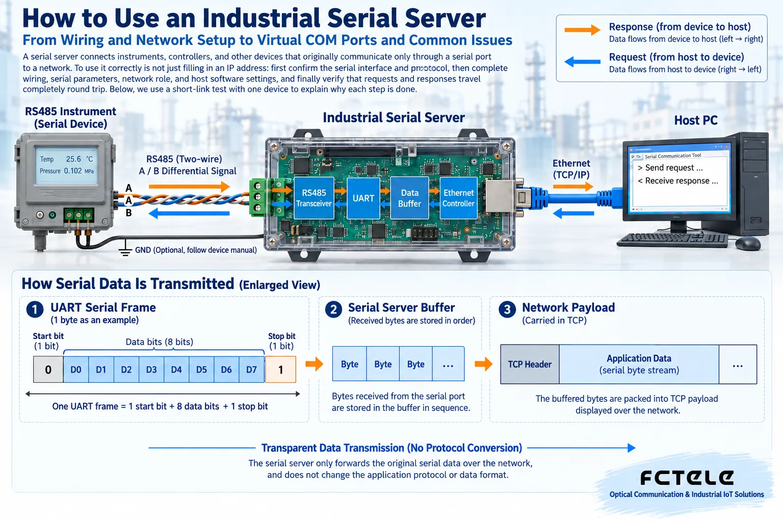
It is suitable for scenarios such as connecting old instruments to a data acquisition system, networking access control devices, and centralized management of building equipment. But networking will not suddenly make an old device support new commands, nor will it replace safety control logic. Medical, power, and critical control systems still need separate verification of isolation, access permissions, response time, and safe behavior after loss of communication; you cannot decide on a solution based only on the words “serial to network port.”
2. Check Interfaces and Wiring Before Power-On
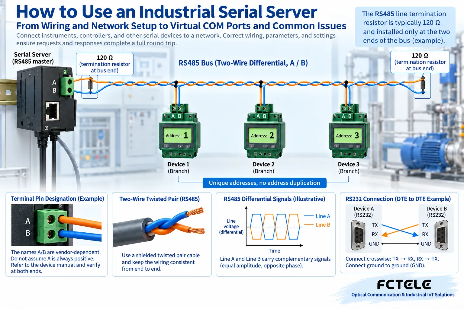
First collect the terminal manual: electrical type, terminal definitions, power supply range, serial parameters, protocol, and device address. The same DB9 or terminal block on the housing does not mean the inside is all RS232. RS232, RS422, RS485, and TTL cannot be directly mixed. Check the power supply voltage and polarity, wire under the specified power-off conditions, and then power on in the manufacturer’s order; do not mistake power terminals for signal terminals.
RS232 is often used for point-to-point communication, and the cable must be checked against the definitions of both sides’ transmit, receive, and reference ground, and sometimes hardware flow control lines are also needed. You cannot judge whether to use a straight-through cable or a crossover cable based only on the gender of the connector. RS422 often uses separate transmit and receive differential pairs, with transmit pair connecting to the opposite side’s receive pair; the specific full-duplex wiring method should follow both manuals.
Common two-wire RS485 lets multiple devices share one bus, usually connected along a trunk with short branches, and it should not be arbitrarily expanded into a star shape. A/B naming may differ among manufacturers, so check the electrical definition rather than just matching letters. Terminating resistors are used to suppress line reflections and should be configured at the physical ends according to cable characteristics, speed, and topology; the common 120Ω is only an example, and you should not add one to every node. Device built-in termination, biasing, and reference ground should also be checked, and the shield and protective grounding should be handled according to the site design.
3. What Serial Parameters and Network Parameters Each Control
Baud rate determines the sending rhythm; data bits, parity bit, and stop bits determine how a group of serial characters is formed. Both sides should use a combination that is consistent and supported by the terminal. For example, 9600, 8N1 means the common 9600 baud, 8 data bits, no parity, 1 stop bit, and it is not the default value for all devices. If the protocol uses parity or a different number of stop bits, follow the protocol and terminal settings; do not change everything to 8N1 just for convenience.
Flow control is used to coordinate sending speed. Hardware flow control may use additional control lines, software flow control uses specific characters, and RS485 also involves switching transmit and receive direction. Changing only the baud rate while missing flow control, interface mode, or direction control may still result in no data. After saving serial parameters, confirm that they have been applied to the correct physical port; with multiple channels, do not mistakenly change another channel.
The network side needs an IP, mask, and, if necessary, a gateway. A static address makes fixed access convenient, but it should be assigned by the network administrator and avoid conflicts; when using DHCP, confirm how the host computer will find the device after the lease changes. For initial debugging, you can put the computer and device on the same subnet in an isolated test network; formal deployment does not have to remain on the same subnet forever: cross-subnet access requires routing and permitted policies, while LAN discovery tools may not necessarily work across routes.
The management web page port and the business TCP port have different purposes. Being able to open the web page does not prove that the serial business connection is successful. Record the management address, each channel’s business port, target address, and working mode, and export the configuration before making changes. After changing the IP, the original page disconnecting may be a normal result; you should access the new address, and do not repeatedly restore factory settings or change all parameters at the same time.
4. Choose the Right Networking Method: Socket, Virtual COM, or Protocol Gateway
TCP Server means the device listens for connections, and TCP Client means the device actively connects to the peer. A common solution is for the serial server to be the Server and the host computer to be the Client and fill in the device IP and business port; it can also be reversed so that the device actively connects to the central server. If both sides listen and no one initiates a connection, no session will be established. These network roles are not the same as Modbus master and slave, and the terminal station number is not the TCP port number.
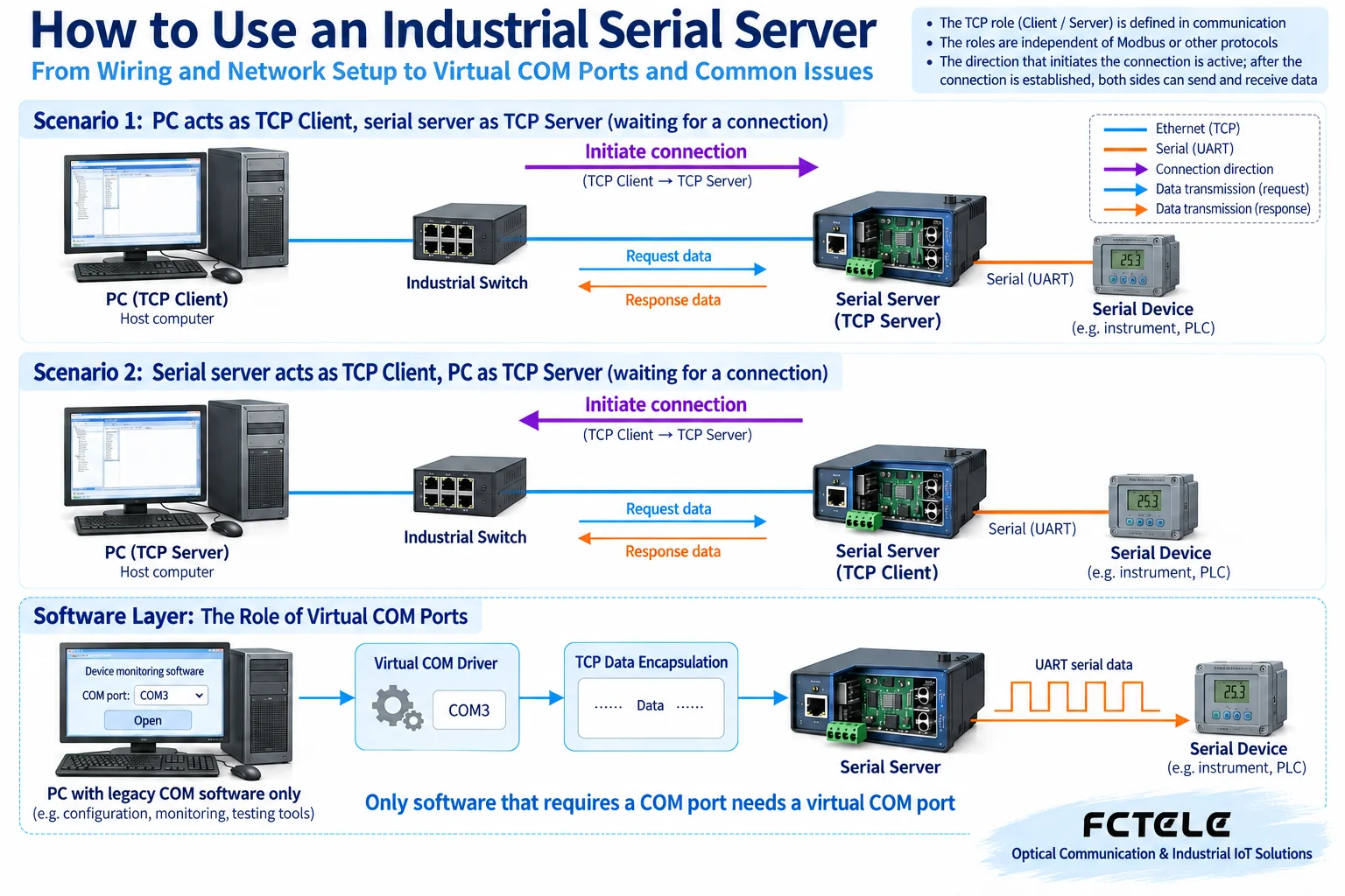
When software can directly use Socket (network communication interface), it can directly read and write the TCP byte stream according to the device mode. Only when an old program only recognizes COM ports is a compatible virtual COM port driver needed to map a local COM number to the network device. After installation, check the driver version, permissions, COM number, mapping address, and port; first exit other programs occupying that COM port, then start the business software.
If the host computer only sends Modbus TCP while the instrument uses Modbus RTU, you need to choose a gateway mode that explicitly supports RTU/TCP conversion and configure the serial port and address mapping. Do not treat transparent pass-through and protocol conversion as the same mode at the same time. UDP does not need to establish a TCP session, but the application should consider loss, duplication, and order changes on its own, and it should not be used for unverified critical control just because configuration is simple.
5. Run Through the Whole Process with a Controlled Example
Assume an RS485 instrument uses Modbus RTU, station number 1, and the manual explicitly supports 9600, 8N1. The host computer software can send RTU request bytes and communicate through a TCP connection. Here, transparent TCP Server is used, not a Modbus TCP gateway; the IP and port are filled in according to the actual planning of the test network, and online addresses are not copied.
Step one: connect only this instrument and the serial server, and check power, interface, and parameters. Step two: assign a valid address to the serial server and enable the TCP Server listening port corresponding to the correct serial port. Step three: the host computer connects to that address and port, and uses a read-only request from the instrument manual to read one known register; do not arbitrarily send write or control commands.
Step four: observe the network session, serial transmit, and receive counts. If transmit increases but receive does not, first check instrument power, wiring, station number, and request format; if both counts increase but the program fails to parse, check the returned bytes, message boundaries, checksum, and timeout. Step five: confirm that the returned value matches the instrument display or known state, then add new nodes one by one, each with a different address, and record whether errors appear after each addition.
If you switch to a host computer that only supports Modbus TCP, you should use the corresponding protocol conversion mode and re-verify the mapping; if the old program can only open a COM port, use the virtual COM port path. Choose only one verified link at a time, and avoid drivers, Socket tools, and multiple masters competing for the same device at the same time, which can cause seemingly random reply errors.
6. Why Common Issues Happen and How to Troubleshoot Them
1. The device cannot be found or the web page does not open
Check the power supply, network port link, the computer’s current network adapter, and the known IP, then check same-subnet conditions, VLAN, and access rules. Multiple network adapters, VPN, or wireless isolation may cause discovery messages to take the wrong path. First check existing configuration, address lease, or the manufacturer’s discovery tool; forgetting the IP does not mean you should immediately press RESET. Restoring factory settings will lose the configuration, so there should be a backup, a downtime window, and on-site authorization.
2. The device is found, but the TCP connection fails
Check the Server/Client role, listening port, target address, and occupied sessions. A successful Ping only shows that some type of IP message is reachable; it does not prove that the business port is open. The firewall should open only the required processes, ports, and source ranges, not turn off all security protection. For cross-public-network access, prefer a controlled VPN or secure access; do not directly expose the management web page and serial control ports.
3. The COM port cannot be opened, or there is no business data after connection
First distinguish between the local COM port being occupied and the remote serial port not responding: for the former, check the driver, mapping, and processes; for the latter, check serial parameters, wiring, station number, and protocol. A successful TCP connection does not prove that the terminal has received the request. Using a known valid read-only request and the raw returned bytes for verification is better at locating the problem than repeatedly clicking “Connect.”
4. Data loses bytes, polling times out, or packets are split or stuck together
Ethernet writes may be much faster than serial sending. Limited buffering, lack of flow control, the application ending too early, or an abnormal disconnection can all cause incomplete business data; TCP’s reliable byte stream cannot guarantee that all data has been sent from the serial port to the terminal. Check the buffering and flow control capabilities according to the model, and have the application limit the sending rhythm, wait for completion conditions, and verify the complete length and content.
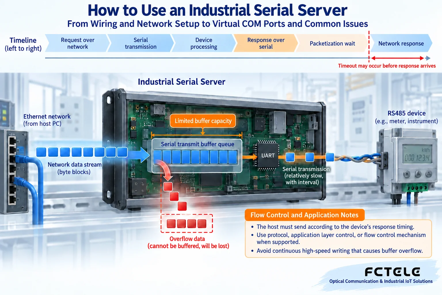
Packetization conditions may be byte count, time interval, or delimiter, and waiting for more bytes will delay network sending. The host computer timeout should cover serial transmission, terminal processing, packetization, and network round trip, and should be measured under actual load. One TCP read may return only half a message or may return multiple messages; the program should accumulate, frame, and verify according to the application protocol, and should not rely on one read equaling one reply.
5. Multiple computers or multiple servers share one port
One central listening port can accept multiple network sessions, but the application still needs to identify which device each session belongs to and handle reconnection, identity, and message source; having only one device ID may not be enough. Multiple computers connecting to the same serial server also does not mean they can simultaneously control the same RS485 slave. One acquisition service should coordinate requests and then distribute results to multiple clients, or use an arbitration solution that is explicitly supported and verified.
7. Selection and Acceptance: Do Not Look Only at “Can Connect”
For selection, first list the actual number of serial ports, electrical standards, protocol, software access method, cable distance, isolation requirements, and site environment, then check the specific model. The Feichang Technology FCT-1500 series details list different serial configurations, virtual COM, and RTU/TCP conversion modes; old software can check the driver method, and when protocols are inconsistent, check the conversion mode. DDM corresponding to optical port configuration can assist in checking module status, but it cannot be used as proof that the serial protocol is correct. Built-in terminating resistors should also be configured according to the actual bus position, not blindly added again.
Acceptance should at least include normal read-only polling, continuous communication under expected load, network interruption and reconnection, device power cycling, address recovery, and multi-node operation. Check the returned content, error counts, maximum response time, duplicate replies, and buffering behavior, not just the link light. Disconnection tests should be performed in an authorized environment; do not unplug cables in a production control system without permission. Save the version, configuration, wiring diagram, test results, and fallback method so that maintenance personnel can reproduce them during handover.
This article serves as an introduction to usage and a complete deployment tutorial; if a fault has already occurred, you can continue reading Layered Troubleshooting of Serial Server Abnormalities. The two articles respectively address “how to connect” and “how to locate faults,” and do not rely on repeated definitions to increase the number of articles.
References:Modbus Serial Line Implementation Guide;Moxa Serial Networking Explanation;Feichang Technology Serial Server Categories,FCT-1500 Product Details. This article consolidates the valid content of the original 1192, 2116, 1983, 2067, 1718, 2059, and 1997; the example parameters do not represent model default values. The principle diagrams are illustrations of general mechanisms and do not represent the actual product or measured results; specific functions are subject to the model, firmware, and manual.
Translated from the Chinese technical article. Source first published: 2019-11-22. Source last revised: 2026-10-13T19:15:07+08:00. Read the Chinese source
