


When choosing a fiber optic transmission device, first explain what service you need to transmit, then check the interfaces and parameters. Fiber is only the transmission medium: being able to connect to the same type of fiber does not mean the device can transmit the same type of signal. Video, telephone, E1, serial port, and Ethernet have different rules and cannot be interchanged just because they are all called “fiber optic transmission devices.”
1. How a fiber optic transmission device moves services to a remote end
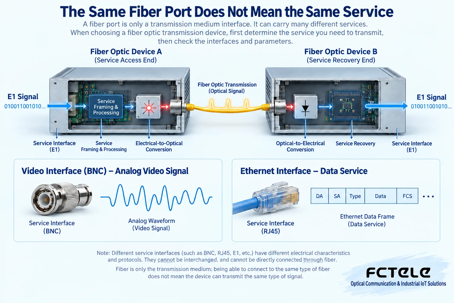
An fiber optic transmission device can be understood as a terminal between service signals and an optical link. The transmitting side receives electrical signals, performs sampling, encoding, framing, or multiplexing according to the corresponding service, and then lets the optical transmitter form a transmittable optical signal; the receiving side converts the optical signal back to an electrical signal and restores the service according to the matching rules. The processing of different products is not exactly the same, and not all fiber optic transmission devices can be described as “converting multiple E1s into optical signals.”
For example, an E1 fiber optic transmission device processes digital circuits, while a video fiber optic transmission device may process analog video, SDI, or other specified formats. A serial port fiber optic transmission device transmits serial electrical signals, and a telephone fiber optic transmission device also needs to match the role of the telephone-side interface. An Ethernet fiber media converter processes Ethernet links. When connecting devices at both ends with fiber, you must confirm that they belong to a pairable series, service, and optical port specification.
2. Analog, digital, compressed, and uncompressed
Analog transmission solutions usually modulate continuously changing service signals onto a signal suitable for optical transmission, and the receiving side demodulates it. Digital solutions represent or carry the service as a digital sequence and then transmit it over a digital optical link. Digital does not automatically mean “all inputs are digital interfaces”: analog audio and video can also be sampled and quantized first, then transmitted over a digital link.
Compression means using encoding methods to reduce the required data volume, which may involve processing delay and trade-offs in image quality; uncompressed means this type of compression is not used, but sampling, framing, and synchronization processes may still exist. When comparing products, you should look at the specific input format, encoding method, end-to-end delay, and test conditions. You cannot claim zero delay just because it is uncompressed, or guarantee no distortion at any distance just because digital technology is used.
3. What do abbreviations like E1, PDH, and SDH mean?
E1 is a type of digital circuit with a nominal line rate of 2.048 Mbit/s. It is not the name of a connector, nor is it equivalent to “Ethernet speed of 2 megabits.” The framing method, clock source, and electrical interface must match together. Whether it provides transparent transmission, alarms, and loopback should be checked in the specific product manual.
PDH stands for Plesiochronous Digital Hierarchy, and SDH stands for Synchronous Digital Hierarchy. Both describe ways of organizing digital transmission, not simple product grades divided by casing or number of interfaces. Actual equipment can carry different numbers of E1s or other services, and the old statement “minimum four channels, maximum over four thousand channels” cannot be used as the capability boundary for all fiber optic transmission devices.
Names such as SPDH may also appear in market materials. When encountering these terms, focus on asking about the optical port format, carried services, compatibility with the opposite end, and networking method. You should not judge whether it can connect to a certain SDH system based only on the name. Standard systems and specific equipment implementations need to be checked separately; similar protocol names do not mean they can be directly interconnected.
4. Connector appearance and electrical rules must be viewed separately
BNC is commonly used for coaxial signal connections and can be used for specified video or E1 interfaces, but two BNCs are not necessarily a pair of transmit and receive ports. You need to look at markings such as TX, RX, IN, OUT, and the specified impedance. Even if video signals and E1 signals both use BNC, they cannot be directly treated as the same service. 75Ω or 120Ω refers to the electrical conditions of the interface, not “the name of this connector.”
The eight-position modular interface often called RJ45 is very common on Ethernet devices, but some communication equipment also uses a similar appearance to connect E1 or other signals. Check the pins, service, and impedance before plugging in the cable. You cannot connect it to a computer’s network port for testing just because a network cable can be inserted; randomly connecting unknown interfaces may cause abnormalities or even damage.
RS232 is a serial electrical interface standard, not a single type of plug. Equipment may use DB9, DB25, or terminals, and the pins and DTE/DCE roles need to be checked. The RJ11 shape is common for telephone interfaces, but the telephone side also has different roles such as FXS and FXO: the interface appearance, power supply, and ringing capability should all be confirmed according to the manual.
SC, FC, ST, LC, etc. are optical connector forms, which are not the same concept as single-mode, multimode, wavelength, and interface rate. The endface polishing type also needs to match, and different endfaces cannot be randomly connected. For dual-fiber, the local transmit must connect to the remote receive; for single-fiber BiDi, the transmit and receive wavelengths need to be complementary, and two ends of the same model are not necessarily a pair.
5. Distance and optical power: do not look only at the nominal kilometers
“Can transmit twenty kilometers” usually includes specified optical modules, fiber, and test conditions. In real engineering, fiber attenuation, connectors, splice points, splitters, and reserved margin must all be included. Transmit power is expressed in dBm, receive sensitivity is the lower limit at which the receiving end can identify the signal under specified conditions; the overload upper limit tells you that too strong an input can also cause failure.
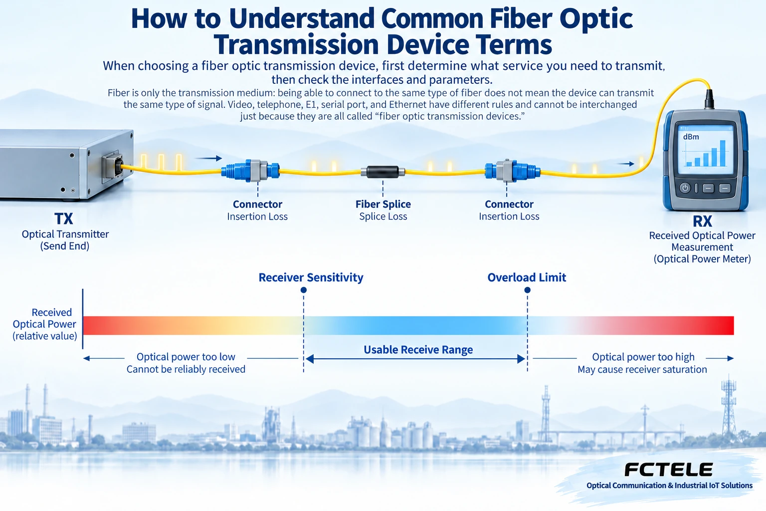
For engineering budgeting, you can first use “minimum transmit power minus receive sensitivity” to get the available loss, then subtract link loss and engineering margin. This calculation is a power budget and does not mean that dispersion, interface compatibility, and service performance have been verified. Before going live, you also need to measure the actual received power and check it separately in both directions; the wavelengths in the two directions of a single fiber are different, and the attenuation reference may also differ.
6. Bandwidth, signal-to-noise ratio, bit error rate, and level
The bandwidth of analog audio and video is often expressed in Hz as the effective frequency range; digital transmission rate is often expressed in bit/s. The two cannot be directly equated, and “larger bandwidth” cannot guarantee that any video standard can be transmitted. When comparing, first confirm the service object, then look at the amplitude, distortion, and other conditions within the specified frequency range.
Signal-to-noise ratio describes the relative size of the effective signal and noise, usually expressed in dB. If the measurement bandwidth, input level, and weighting method are different, digital values cannot be directly compared horizontally. Bit error rate is the ratio of the number of erroneous bits to the total number of tested bits; the observation duration, code pattern, and environment need to be recorded together. Not seeing errors for a while does not mean there will always be zero errors.
Signal level should specify the object, unit, and reference value. dB represents a relative ratio, dBm uses one milliwatt as the reference, and voltage amplitude may also be expressed in V or Vpp; they cannot be mixed up. Impedance matching affects signal reflection and waveform, and it is not something that can be proven qualified for a high-speed interface just by measuring DC resistance.
7. Turn terminology into selection and acceptance questions
Provide the manufacturer with input equipment, output equipment, service format, interface pins, distance, fiber core resources, and environmental conditions. Ask them to explain how the two ends pair, which parameters are typical values, and which are guaranteed ranges. After receiving the equipment, first perform a controlled short-link test, check the optical power, then connect to the site and verify the actual service, alarms, and recovery.
The Feichang Technology product center lists PDH, SDH, telephone, and dedicated service fiber optic transmission devices separately. When selecting, you should enter the corresponding category to check the specific model. Each interface of a multi-service device also needs to be verified separately; “integrated services” cannot replace detailed specifications.
References:ITU-T G.703,ITU-T G.707,Feichang Technology product category entry. This organizes the interface and parameter content in 1468, 1403, and 2156, and corrects service generalization and formula misuse. The schematic diagrams are general illustrations and do not represent actual products, measurements, or model specifications.
Translated from the Chinese technical article. Source first published: 2020-06-15. Source last revised: 2026-10-13T19:28:50+08:00. Read the Chinese source
