


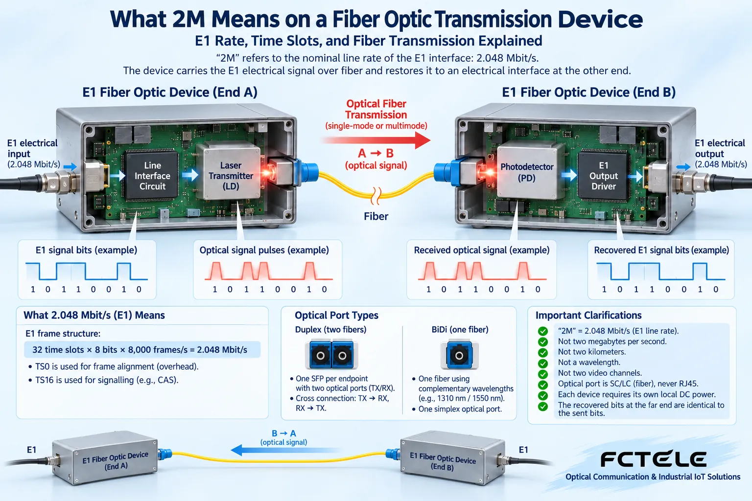
In fiber optic transmission device documentation, “2M” usually refers to the nominal line rate of the E1 interface, 2.048 Mbit/s. It is not two megabytes per second, not two kilometers, not a certain optical wavelength, and not two channels of video. An E1 fiber optic transmission device carries an E1 electrical signal that meets its requirements over a fiber link to the other end, and then restores it to an electrical interface. Only by understanding the differences between rate, frame structure, and transmission medium can you know whether two devices can truly be paired.
Bits, bytes, and distance are not the same thing
A bit is the basic unit of digital information, often written with a lowercase b; a byte usually consists of eight bits and is written with an uppercase B. Therefore, if 2.048 Mbit/s is converted only on the basis of eight bits per byte, what you get is the line bit stream equivalent of 256,000 bytes per second. This is not necessarily the speed that an application file will achieve, because actual services may also use frame structure, control information, or upper-layer protocols.
“2M” describes how many bits a signal sends per second, “how many kilometers” describes the distance a link can cover, and “how many nanometers” describes the wavelength of light. They can appear in the same parameter table at the same time, but they cannot replace one another. For example, two devices with the same line rate may still fail to pair because their optical interfaces, wavelengths, single-mode or multimode type, or service formats are inconsistent. Similar names are only the starting point for checking, not a conclusion of compatibility.
Why E1 is exactly 2.048 megabits per second
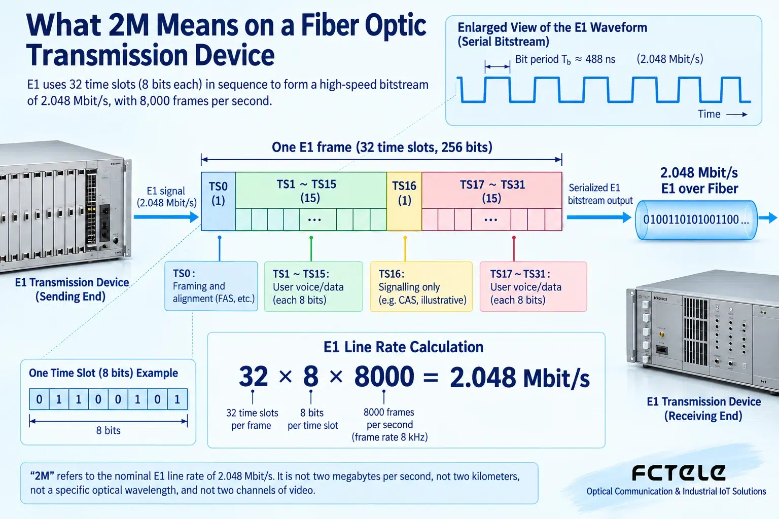
When understanding framed E1, you can think of the continuous bit stream as fixed-length small cells sent out repeatedly. One frame has 32 time slots, each time slot occupies 8 bits, and 8000 frames are sent per second. Therefore, 32 times 8 and then times 8000 gives 2,048,000 bits per second, which is 2.048 Mbit/s. One time slot corresponds to 64,000 bits per second, but what service it is used for still depends on the device and the framing method.
This kind of “time-sharing” arrangement is called time division multiplexing: different channels appear in turn at prearranged positions. The receiving end knows the meaning of each position, so it can separate the channels. It is not that 32 channels simultaneously compete for one line, nor that each channel sends whenever it is free. The positions and rhythm of the cells must be understood by both ends together, which is why frame synchronization and clocking are important.
Why 32 time slots cannot simply be called 32 telephone channels
Time slot zero usually carries structural information such as frame synchronization, allowing the receiving end to identify where a frame begins. In common configurations using channel-associated signaling, time slot sixteen can carry signaling, and the remaining channels are used for voice, so the saying of 30 telephone channels is often seen. However, different signaling and data-bearing methods may use time slots differently, and every E1 line cannot be uniformly identified as 30 telephone channels.
It is also necessary to distinguish framed from unframed. Framed equipment recognizes structure and time slots and can select services according to the supported methods; unframed transmission tends to carry a continuous bit stream. The same electrical interface rate does not mean the same service format. When it is necessary to connect to telephone multiplexing equipment, the specific signaling and channel arrangement should be confirmed; when it is necessary to carry data, the mapping and interface methods at both ends should be confirmed. Checking only that “both are 2M” will miss the truly critical conditions.
What exactly changes inside the fiber optic transmission device
The transmitting end first receives the E1 electrical signal and, according to the design, completes electrical interface reception, signal conditioning, and optical transmission processing. The fiber carries the modulated light to the opposite end; the optical-to-electrical receiving circuit at the opposite end restores the data and, as required, re-forms the E1 electrical interface output. What the device carries is the digital sequence and the corresponding timing relationship. It does not directly put the sound of a telephone call into the fiber, and it is not necessarily responsible for understanding the full meaning of telephone signaling.
This process involves two boundaries: electrical compatibility and optical link compatibility. The E1 interface may use different impedances and connection forms, which must be matched according to the device instructions; for the optical interface, the fiber type, wavelength, direction, and optical power range must be checked. Some devices have loopback or bit error testing capabilities, and some support remote status viewing. Whether a function exists and how it is used must be based on the actual model, and should not be inferred from the same category name.
How to distinguish E1 interfaces, Ethernet ports, and video interfaces
E1 is a digital line interface that works at a specified rate and timing. Ethernet uses frame communication, and its port nominal rate cannot be directly treated as E1 capacity. An E1-to-Ethernet device also needs to map Ethernet frames into the supported E1 channels, so even if it has a 100 Mbit/s network port, the E1 side will not gain a 100 Mbit/s line rate out of thin air. The effective application speed will also be affected by mapping, buffering, and protocol overhead.
For video fiber optic transmission devices, it is first necessary to confirm whether the object is analog video, SDI, or network video. It may use different internal processing and optical link designs. A certain integrated service device can indeed transmit multiple services at the same time, but that is the capability of a specific configuration. It does not mean that any E1 fiber optic transmission device connected to a camera can transmit pictures. The same connector shape cannot replace electrical and service definitions, and in particular, an RJ45 shape must not be uniformly understood as Ethernet.
How should Feichang Technology products be selected according to the task
The FCP-E product on the Feichang Technology official website is used for corresponding E1 optical transmission scenarios; the FCP-E4m product on the official website belongs to the multi-channel E1 transmission product category, and a solution can be checked around its listed channel, alarm, and remote test capabilities. Single-channel and multi-channel products solve different scales, and they cannot be compared only on the basis that “both have optical ports.” Specific impedance, pairing method, and optional functions should be based on the delivered configuration and manual.
If the site is an E1 circuit extended to another building, the interfaces and service formats of the external devices at both ends should first be clarified, and then the corresponding pair of optical transmission devices should be checked. If the site needs to put network data into an existing E1 line, then the protocol converter product category should be examined, rather than directly buying a pair of ordinary fiber optic media converters. First describe what needs to be carried, and then choose the device responsible for carrying it. This is usually more reliable than choosing by appearance first.
Why clocking also affects services
Digital reception cannot only know which zeros and ones there are; it also needs to know at what moment to judge each bit. The clock can be understood as the basis for reading the cells according to rhythm. When two devices use an inappropriate clock relationship, the physical signal may be present, but long-term services may still have bit errors or slips. Who provides it, where it is recovered from, and how it is set must be confirmed according to the system design and device instructions.
Therefore, troubleshooting must not arbitrarily change the clock mode when the original configuration is unclear. First record the line status and alarms, and then follow the maintenance procedure to distinguish the local interface, the optical section, and the remote interface. If loopback is used, it proves the performance of the selected test path, and does not automatically prove that telephone calls or data applications are all normal. The clearer the test path, the easier it is to separate “the light is on” from “the service is correct.”
From short-distance pair testing to on-site acceptance
For a new deployment, you can first use a short fiber that meets the device requirements and a known-good E1 service to establish a baseline, check the pairing direction and interfaces, and then connect to the formal link. Acceptance should examine not only signals and alarms but also services, such as actual calls, data transmission and reception, or bit error test results. A link distance meeting the advertised value does not mean that endface contamination, splice loss, and interface mismatch will not occur.
Finally, record the line rate, framing method, time slot usage, interface impedance, clock relationship, and optical parameters in the delivery materials. As long as maintenance personnel can check along the line of “service format – electrical interface – optical transmission – remote restoration,” they will not easily misjudge a capacity problem as a wavelength problem. The so-called 2M is not a vague product grade, but rate information for a specific digital line. It has practical meaning only when placed in the complete link.
Verification materials:Feichang Technology FCP-E;Feichang Technology FCP-E4m;ITU-T G.704;ITU-T G.703. The diagrams explain general mechanisms and are not wiring diagrams for specific models.
Translated from the Chinese technical article. Source first published: 2020-01-06. Source last revised: 2026-10-13T22:21:36+08:00. Read the Chinese source
