


Twisted pair twists two insulated conductors together in a certain way and is widely used for Ethernet, serial buses, and other connections. It is not a universal protocol, and it cannot make any signal extend indefinitely. Understanding how the two wires carry information together, why the pair and impedance must be maintained, and how different devices use the pair is what explains many intermittent problems.
What twisting together changes first
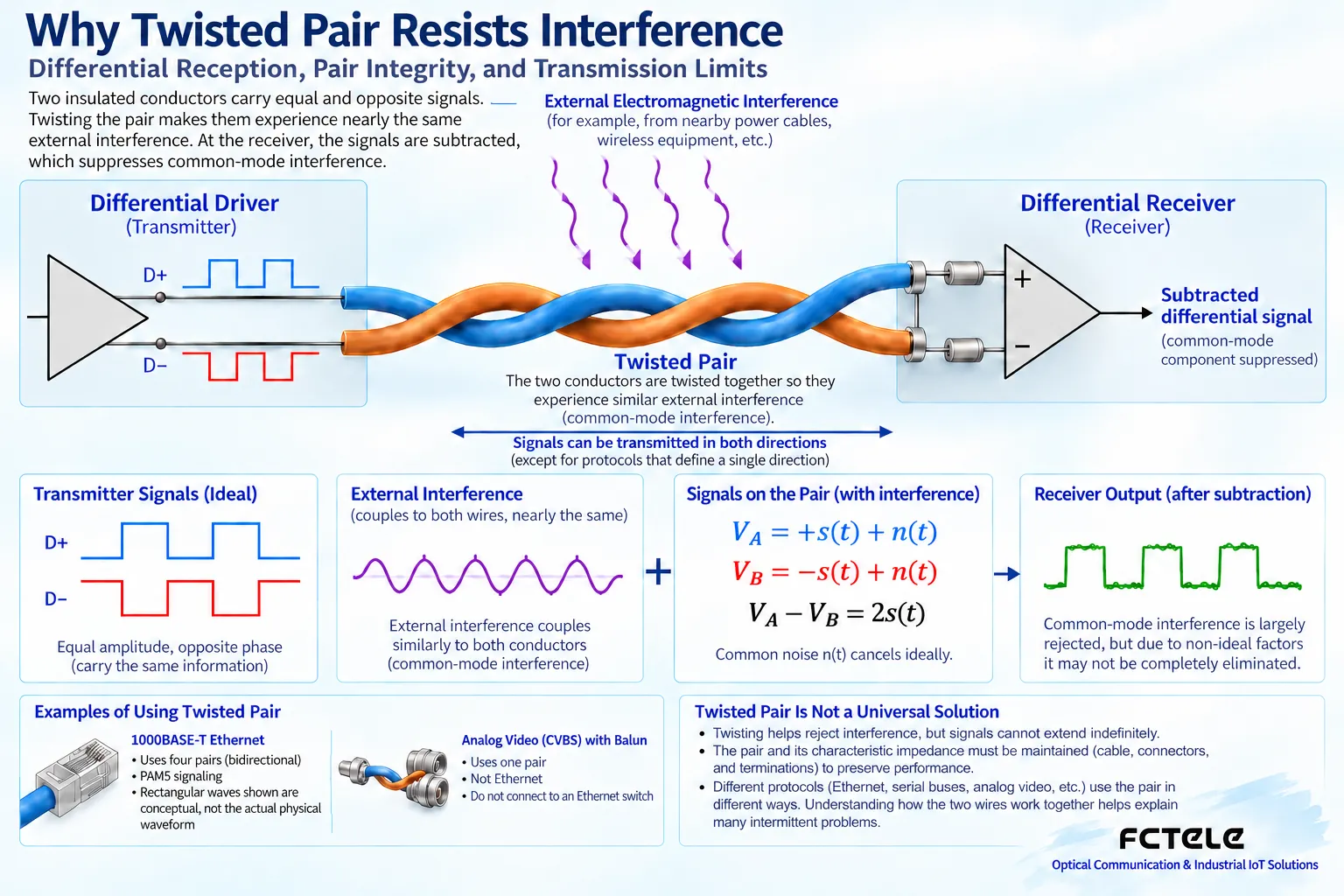
When two wires are brought close together in space and periodically exchange positions, the conditions under which they are exposed to external interference become more similar, and this also helps control the electromagnetic characteristics of the pair. An ideal differential receiver looks at the difference between the two wires and has the ability to suppress certain interference that appears on both wires at the same time. You can think of it as finding the difference between two similar measurements, rather than treating external noise directly as data. Real-world imbalance, strong interference, and going beyond the receiver range can still cause problems; twisting is not magic that completely eliminates all interference.
Differential signals cannot be understood as two independent circuits
A pair of wires together forms the specified signal path, and the receiver needs to interpret them according to the protocol’s electrical conditions. Arbitrarily pulling out one wire and moving it to another pair will break the original conditions. Common-mode voltage and differential voltage are also different: the two wires shifting together relative to a reference point and the difference between the two wires changing are not the same thing. Some systems also need suitable reference connections and isolation design. Do not assume that because differential signaling is used, the potential difference between devices can be ignored; exceeding the device’s allowed range can still damage equipment or cause errors.
Why can’t the eight wires in a network cable be paired arbitrarily?
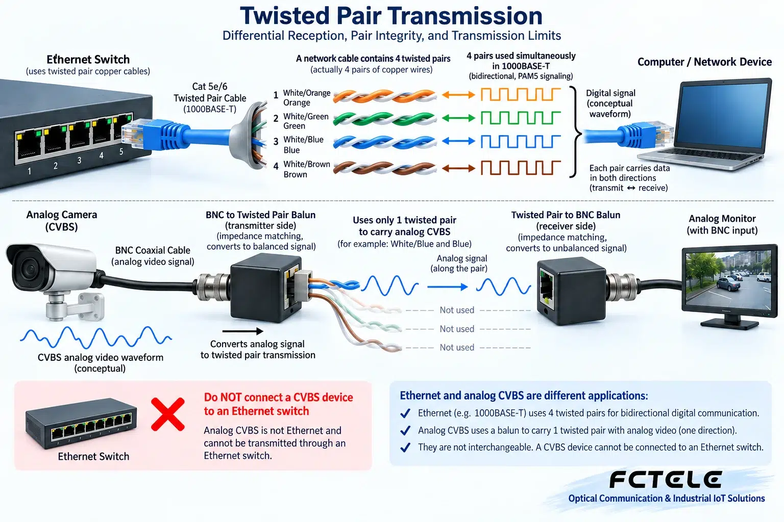
The wiring of common four-pair twisted-pair Ethernet cables specifies which contacts each pair corresponds to. Connecting all eight conductors does not mean the pair relationships are correct; split pairs may look normal in a simple continuity test but cause high-frequency transmission problems. Gigabit copper Ethernet uses all four pairs, and you cannot carry over the understanding from some 100 Mbps scenarios to split off so-called spare wires. Fabrication and acceptance should use applicable cabling standards and corresponding tests, not just a multimeter to check continuity. Excessive untwisting at connectors can also affect link performance.
Why does impedance make signals reflect?
When a rapidly changing signal propagates along the line, the cable and connections behave as a transmission system. When the end or an intermediate structure does not match the design conditions, part of the energy reflects and adds to later signals, making interpretation harder. It is a bit like a wave returning after reaching an unsuitable boundary, but you cannot use this metaphor alone to derive a specific resistance value. Ethernet, RS485, and analog video have different interface methods, so their termination measures are also different. You cannot arbitrarily connect an RS485 termination resistor across every network port, and you certainly cannot wire everything uniformly just because they all use twisted pair.
What should be noted in RS485 wiring?
Two-wire half-duplex RS485 usually requires handling the line, branches, termination, and biasing according to a bus design. Typical termination matches the cable’s characteristic impedance and is placed at the appropriate ends of the bus, not added to every device. Actual line length, rate, branches, and number of devices affect one another; a advertised maximum distance cannot be used without conditions. The naming of A and B may also differ because of manufacturer definitions, so checking the documentation is more reliable than guessing polarity from the letters. Devices on the bus should transmit in time slots according to the application rules; multiple nodes driving at the same time will cause conflicts.
Using a network cable to carry analog video does not turn it into network video
Some analog video schemes use adapters to carry signals such as CVBS over specified pairs, and the adapter performs the appropriate electrical matching. This line is still the corresponding analog signal chain, and it does not become Ethernet data just because a network cable is used. It cannot be connected to an ordinary switch expecting automatic forwarding, and it cannot be assumed to be compatible with Gigabit networks and PoE on the same cable. You should find out the adapter type, video format, distance conditions, and receiving device. An analog camera transmitting through a video fiber optic transmission device and an IP camera uplinking through a network fiber optic transmission device are different processes.
Feichang Technology devices should be matched according to their real interface roles
The official description of Feichang Technology FC-2001 is a USB to RS485 interface converter with automatic direction handling; serial optical modem products provide optical transmission options for the corresponding RS232, RS422, or RS485 channels. The former helps a computer connect to an electrical bus, while the latter helps transmit serial information across segments; they cannot be treated as the same thing. Using fiber to cross segments also requires separately handling termination and grounding for the local copper bus at both ends. This article only cites verified functional directions and does not describe these products as universal converters for any video or any network signal.
Why does shielded cable also need correct installation?
The shield helps handle specific coupling conditions, but how it is connected is related to the entire grounding and equipotential system. Incorrect connection may introduce new loops, and you should not simply declare that in any scenario it should be connected at only one end or at both ends. Separation of power and low-voltage lines, cable routing, device isolation, and protection are equally important. Grounding at a retrofit site should be implemented by qualified personnel according to standards, and protective grounding must not be disconnected just to eliminate noise. Choosing shielded cable also does not mean you can ignore connectors and pair integrity; the balance of the complete system determines actual performance.
How to preserve useful evidence for intermittent connections
First record the conditions under which the error occurs, the link rate, interface counters, and device status. Use a verified short cable and corresponding device combination to establish a baseline, then add the original cable length and on-site cabling segments. For Ethernet, observe errors and throughput; for RS485, check messages, response time, and serial parameters; for analog video, observe the picture and waveform. You cannot uniformly just run Ping. Change only one variable at a time and write down the changes after swapping cables. If the fault appears only when a motor starts, also check power and interference at the same time, to avoid blaming all problems on the signal line.
Acceptance should not leave only ‘it is connected’
Delivery should note the cable category, actual route, connectors, interface standard, target rate and load, and test results. For long distances or complex environments, a suitable fiber solution may be considered, but fiber does not replace local power and interface matching. When expanding later, recheck the load and pair usage, and do not add different services to a line without evaluation. Reliable twisted-pair transmission comes from correct electrical conditions, installation that maintains the pairs, and verification for the corresponding service. Understanding these three levels allows you to both explain the cause of interference and avoid unnecessarily replacing equipment.
Product and principle verification materials:Feichang Technology product details 2336;Feichang Technology product details 611;Principle verification material 1. The general mechanisms and hypothetical examples in the main text do not replace the corresponding model manuals.
Translated from the Chinese technical article. Source first published: 2020-01-19. Source last revised: 2026-10-13T22:21:36+08:00. Read the Chinese source
