


Network topology describes how devices are connected and what path data actually takes when it is forwarded. Star, daisy-chain, ring, tree, and mesh topologies each have their own failure scope and cost boundaries. Physical cables connected into a ring do not mean data can loop endlessly on every link; Ethernet rings require clear control or protection mechanisms.
First, separate “physical” from “logical”
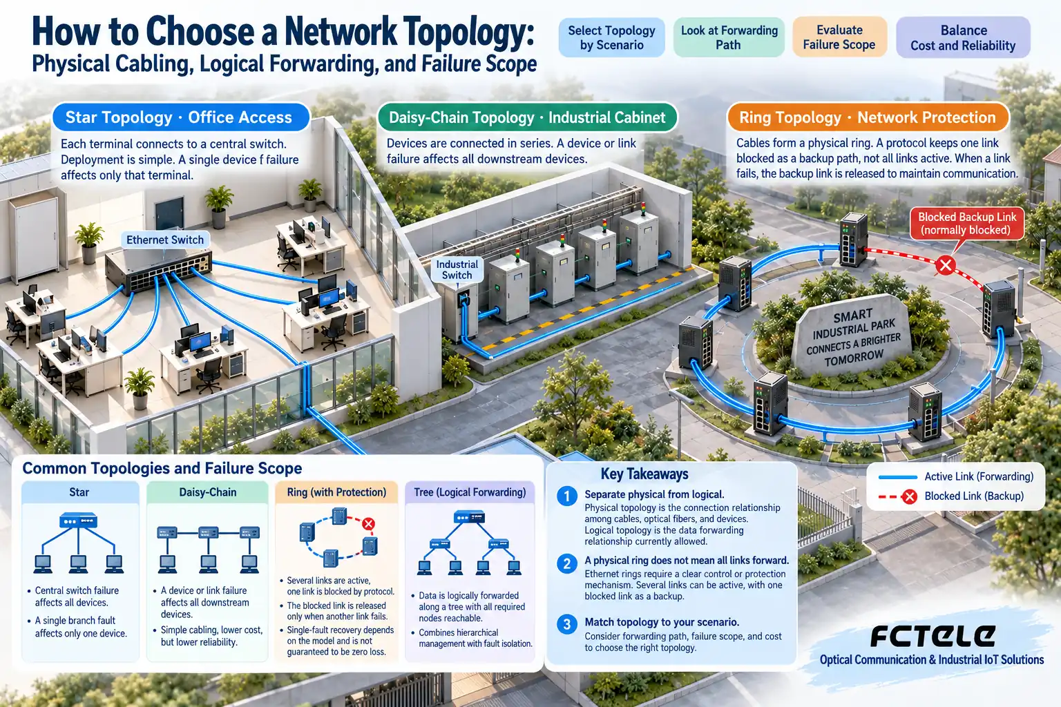
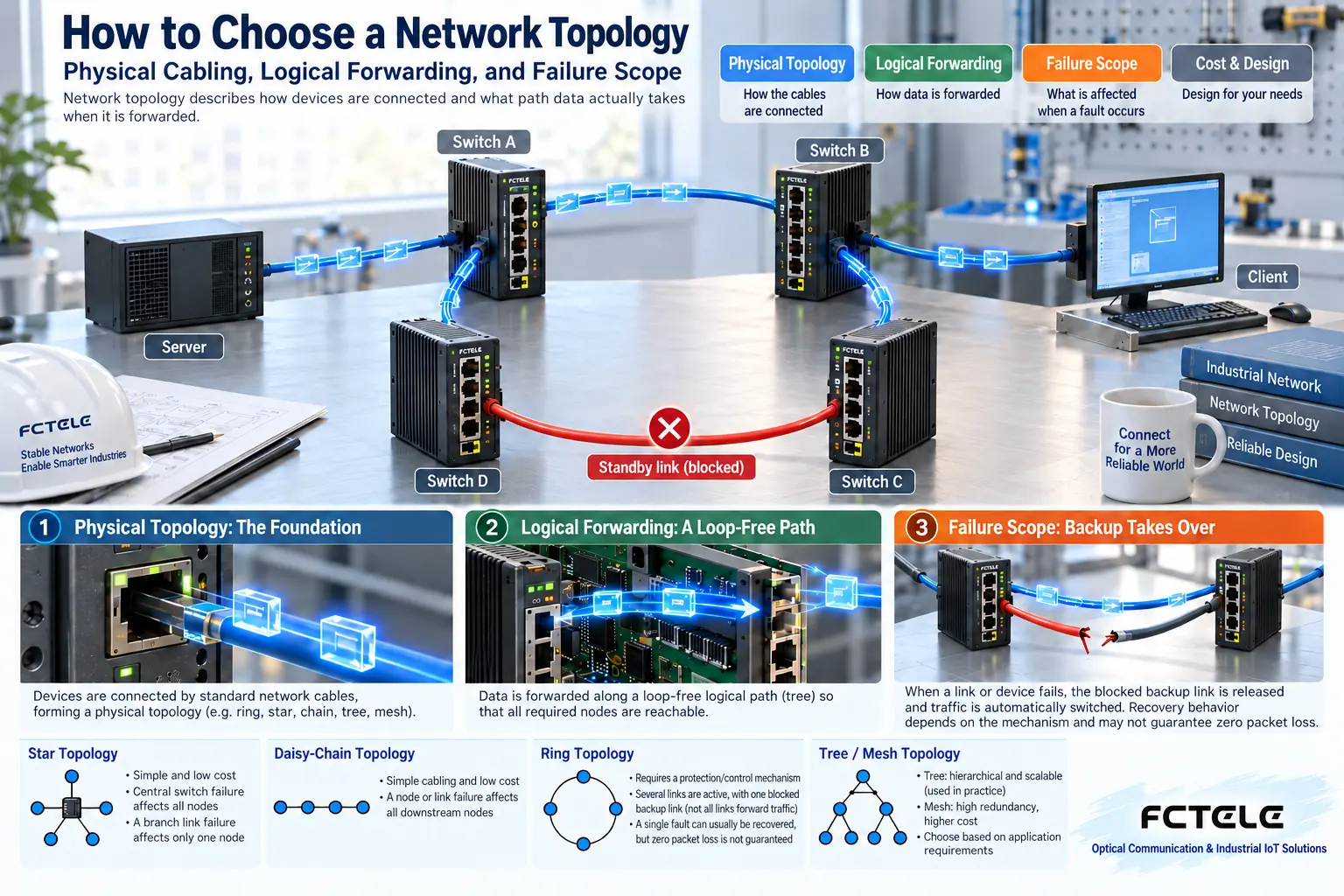
Physical topology is the connection relationship among cables, optical fibers, and devices. Logical topology is the data forwarding relationship currently allowed. If four switches are cabled in a ring, a protection protocol may keep one segment as standby, so normal data does not travel around the complete physical ring.
Another common misunderstanding is treating VLANs as a cabling shape. The same physical network can carry different VLANs, and each broadcast domain has different members and forwarding boundaries. Drawings should note devices, ports, and service relationships at the same time; drawing only cables is usually not enough to explain the system.
Star: clear connections, but the center deserves attention
Terminals connect separately to a central switch, making additions and troubleshooting relatively easy. If one terminal cable breaks, it usually affects the corresponding terminal; if the central device or central power fails, the impact may extend to all connected access devices. Plan the central device, power, and uplinks according to business importance.
In actual engineering, multiple access stars are often aggregated to upper layers, forming a tree structure. This makes regional management easier, but aggregation links may become bandwidth or failure concentration points. It is necessary to estimate the traffic at each layer and the number of downstream devices, not just whether the lowest-layer ports are sufficient.
Daisy-chain: saves cabling, but later nodes share the earlier segment
Connecting section by section along a road or continuous cabinets can simplify some cabling. If an earlier link breaks, multiple later nodes may become unreachable at the same time; each segment’s capacity may also carry more aggregated services. During design, clearly define the worst-case failure scope and maintenance access points.
Historical shared-medium buses, RS485 buses, and switched Ethernet daisy chains are not the same network mechanism. They may look similar on a diagram, but they have different electrical and forwarding rules. The serial bus termination resistor method cannot be directly applied to Ethernet links.
Ring: redundant cables must work with a protocol
If ordinary Layer 2 Ethernet is directly closed into a loop, broadcasts and unknown unicasts may be copied repeatedly, causing network congestion. Spanning tree or corresponding ring network mechanisms avoid loops by controlling the forwarding path and reopen paths under specified fault conditions.
The device capabilities, configurations, and compatibility of different protocols cannot be assumed to be the same. When choosing a ring network, clearly define the standard or proprietary protocol, node roles, fault detection, and service scope. Recovery results need to be tested under actual load. Double faults or node power loss may exceed the single-link protection assumption.
Mesh does not mean every line can be used at the same time
Multiple paths can add optional connections, but they also increase ports, cabling, and control complexity. Whether Layer 2 mechanisms or Layer 3 routing are used affects how multiple paths are utilized. Link aggregation also requires corresponding configuration; simply plugging in two parallel network cables does not double service speed.
Shared power, equipment rooms, conduits, or central devices may cause seemingly independent paths to fail at the same time. These common failure points should be identified in drawings; otherwise, the topology may look very complex while in reality there may still be only one critical dependency.
Choose based on business needs, not by memorizing shapes
List terminal distribution, capacity, allowed interruption, maintenance methods, and cabling conditions, then evaluate normal and fault paths. A simple star may be most suitable for a small network, while layered or ring networks require corresponding configuration and acceptance capabilities. You can check interfaces, protocols, and management functions in the Product Center.
Finally, keep records of normal paths and specified post-fault paths, including service recovery and not only light status. Topology diagrams must be updated as the site changes, to avoid making wrong judgments based on outdated port relationships during maintenance.
Translated from the Chinese technical article. Source first published: 2022-11-04. Source last revised: 2026-10-13T20:54:09+08:00. Read the Chinese source
