


To judge the quality of a fiber optic transmission device, you cannot look only at optical power, and you cannot understand “has been aged” as a guarantee of lifespan. Optics, electrical interfaces, service recovery, and load environment each have their own inspection methods. When purchasing, what is more worth requesting is records of the corresponding model, version, and test conditions, as well as an acceptance plan that can be rechecked on site.
1. Testing must first clarify the service being tested
Video fiber optic transmission devices, E1 fiber optic transmission devices, and serial fiber optic transmission devices handle different signals and cannot share one vague conclusion of “transmission normal.” First record the model, serial number, hardware and firmware version, interface configuration, optical version, and power supply, then list the services to be verified. If a test report does not have this information, even if there are many items, it is hard to match to the actual purchased equipment.
Component incoming inspection, circuit board inspection, complete machine factory inspection, and on-site acceptance are different stages. A single optical module passing does not mean assembly, interfaces, and service recovery all pass; a complete machine passing a certain test in the factory does not automatically prove that all on-site lines and terminals are correct. Quality evidence should connect these stages, rather than replacing all processes with one stamp or one photo.
2. What an optical power meter can tell us
An optical power meter measures the received optical power at a selected wavelength and under suitable connection conditions. It can help check transmitted light and link loss, but it cannot directly prove that video colors are correct, that serial protocols are compatible, or that E1 clocking is stable. Before measurement, you need to confirm the instrument range, wavelength setting, connector cleanliness, and measurement location; you cannot directly compare a value under unknown conditions with the manual.
The receiving end requires optical power to be between sensitivity and overload. Transmitted light looking very strong is not necessarily an advantage; input that is too strong may also fail to recover correctly. Checking power and checking service are two complementary tasks: one describes the optical conditions, and the other checks whether the system correctly handles the actual signal.
3. How adjustable attenuation helps verify margin
An adjustable optical attenuator reduces optical energy in a controllable way, and is used to observe the performance of the receiving end under different input conditions. It is not an amplifier, and it cannot repair an already damaged signal. A test bench can consist of a specified signal source, transmitter, attenuator, receiver, and analysis equipment, changing one variable step by step under safe maintenance conditions.
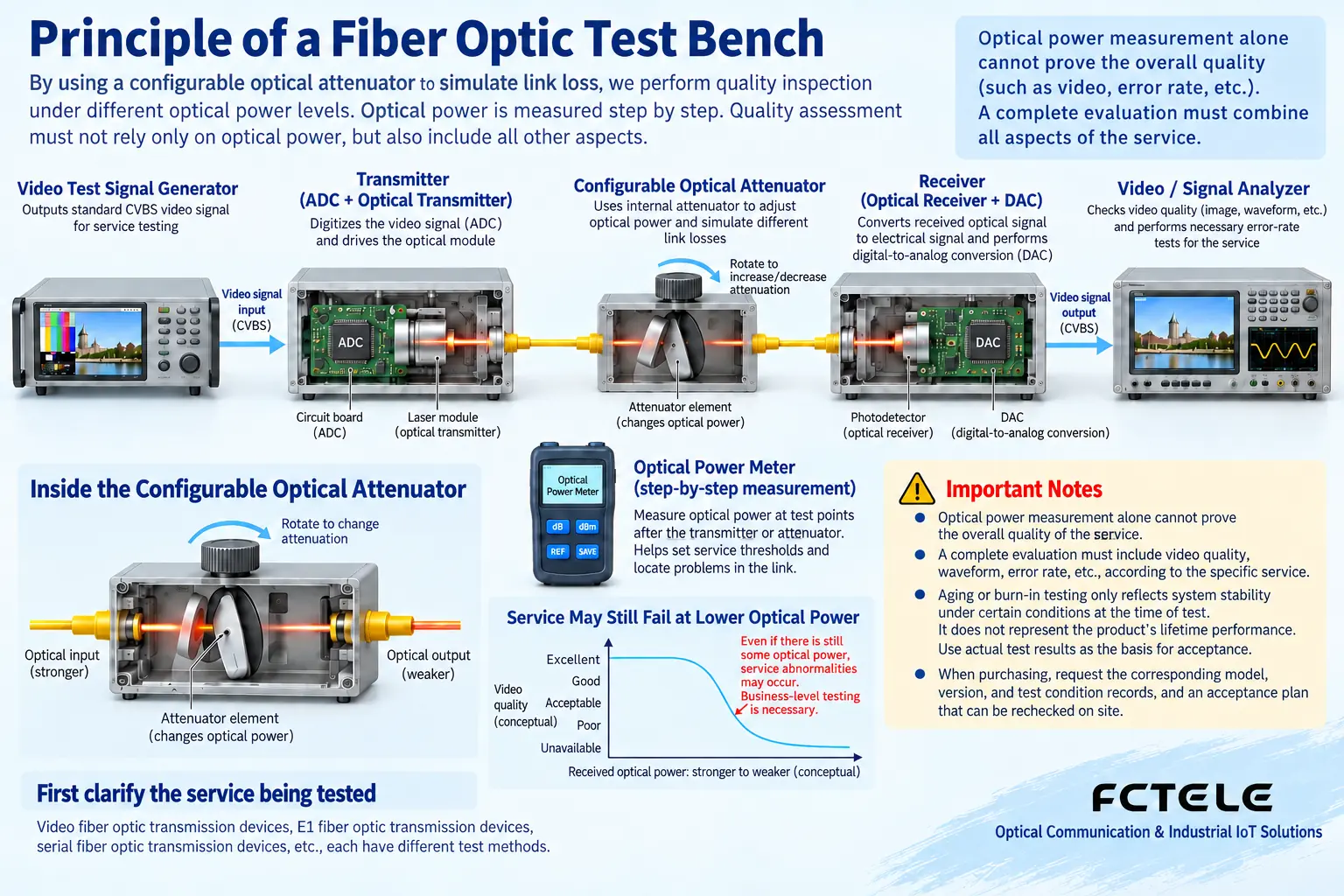
A long reel of optical fiber has other propagation characteristics besides loss. An adjustable attenuator mainly changes power, and the two cannot be completely equivalent in all tests. To claim performance at a certain distance or with a certain fiber type, you need to state the actual fiber, wavelength, connectors, and test method; you cannot use “attenuation equivalent” to prove all long-distance behavior.
4. Service testing cannot just take one pretty picture
Analog video should be checked for synchronization, detail, light and dark changes, color, and noise according to the agreed standard and conditions; when professional instruments are available, verify indicators according to the corresponding method. E1 should focus on the electrical interface, coding, clocking, bit errors, and alarms; serial ports should use real commands and responses to check direction, configuration, and service results. The test bases for different services cannot be mixed.
Multi-channel equipment also needs to verify the planned concurrent combination. Testing only one video channel cannot prove that other channels, reverse control, and audio still meet requirements when working at the same time. If a function is optional, the test report should clearly state whether this unit is equipped with it, and the series name should not be allowed to hide actual hardware differences. During trials, save information about the signal source, receiving terminal, and cables, so that repeated comparisons are easy.
5. Why aging screening helps and also has limits
Aging screening usually lets equipment run continuously under specified load and environment, monitoring whether abnormalities appear. It helps expose certain early defects, assembly problems, or heat-related abnormalities, but the effect depends on the conditions and judgment method. You cannot attribute all failures to the first few hours, and even less can you assign a fixed test temperature and duration to all products without basis.
Equipment power consumption generates heat, and heat is dissipated through the circuit board, thermal conduction structure, and enclosure. If load increases or the environment changes, the operating conditions of the power supply and chips also change. Recording temperature, power supply, alarms, and service errors during continuous operation is more meaningful than only recording “has been powered for a certain number of hours.” The location of temperature sensors and the test configuration should also be clearly stated.
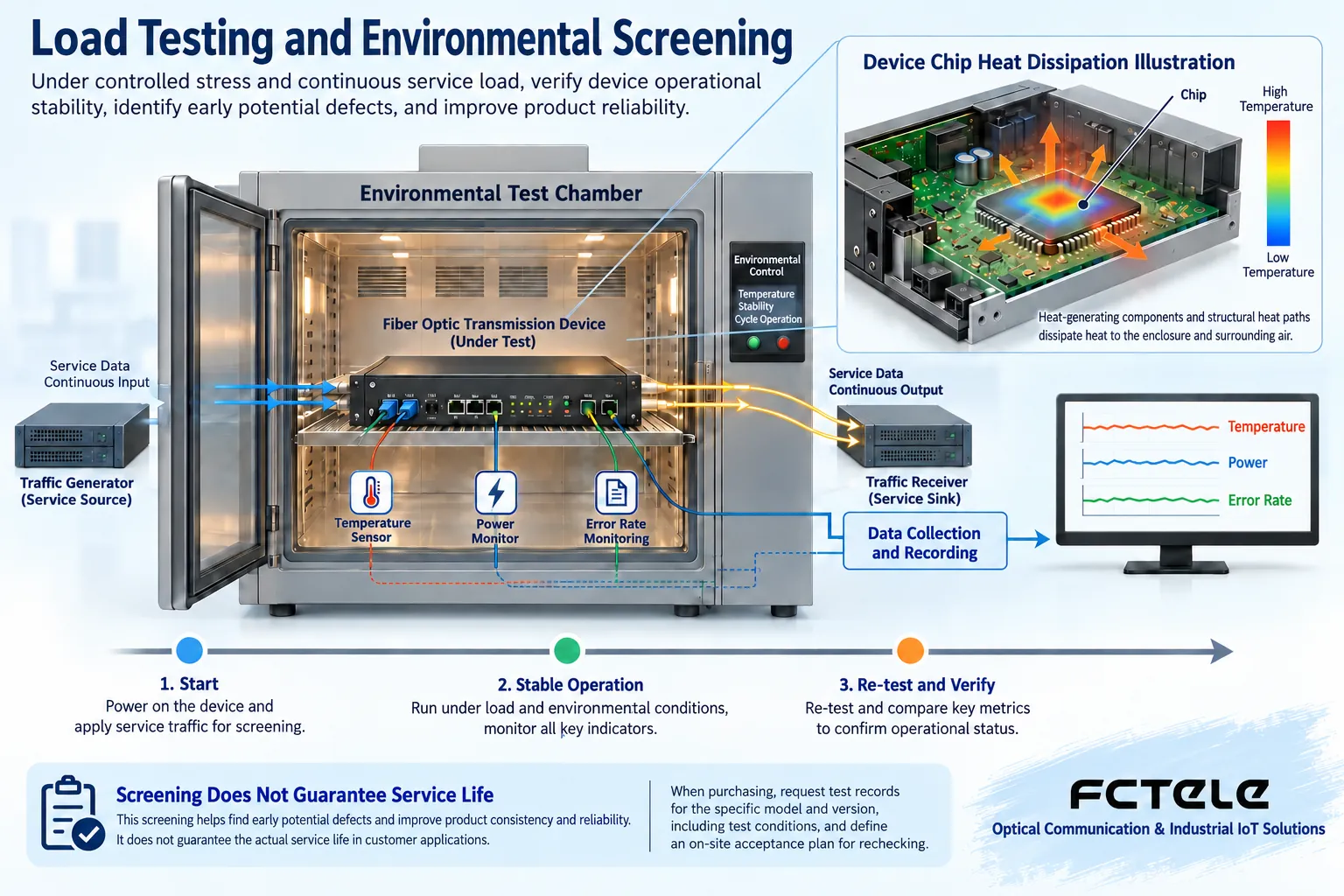
Aging testing is not equal to reliability qualification, nor is it equal to life testing. Lifespan inference requires support from a corresponding model, samples, and conditions; you cannot infer years of zero failure from a few devices that did not go wrong. Stress testing beyond rated conditions may also damage equipment, and should be completed by professionals according to an approved plan; users are not advised to perform heating or overvoltage tests themselves.
6. How procurement should require useful quality evidence
Confirm with the manufacturer the model version, test object, samples, method, conditions, instruments, and judgment criteria corresponding to the report. Third-party reports also need their coverage checked; you cannot treat one EMC item as certification for all lightning protection and all environments, and even less can you treat a report for another model as complete proof for this model.
Feichang Technology Video product details Can be used to confirm the required interfaces and configuration; actual procurement should also request test and acceptance materials for the corresponding ordered version. This article does not describe a general testing process as an unverified Feichang Technology production process, and does not infer that every product has undergone aging for a fixed time.
7. Connect on-site acceptance with subsequent maintenance
After arrival, first check the serial number and configuration, use real terminals to establish a short-link baseline, and then connect the on-site optical cable. Record received power and service results, and cover the planned multi-channel concurrency and agreed recovery process. When a problem is found, keep the conditions at that time, and do not replace cause analysis with repeated restarts to clear alarms.
Associate acceptance records with the maintenance baseline, so that later changes can be compared. What procurement really needs is clear capability boundaries, traceable testing, and executable service, not treating “strict quality inspection” as an unconditional reliability promise. Only by knowing what each test proves and what it does not prove can you make judgments with evidence.
Reference Fiber optic connection inspection materials and corresponding manufacturer product descriptions. The figures are general principle illustrations, not factory photos, test reports, or measured curves.
Translated from the Chinese technical article. Source first published: 2020-06-03. Source last revised: 2026-10-13T18:52:49+08:00. Read the Chinese source
