


Common copper Ethernet PoE solutions are designed for a maximum 100-meter channel, but this number is not a safety guarantee under any cable, power, and temperature. PoE distance is limited by both data transmission and power loss. Sites farther away usually need the link to be replanned, for example a fiber uplink with remote local power, rather than extending the cable and expecting the function to stay the same.
100 meters refers to the entire channel, not just one cable segment
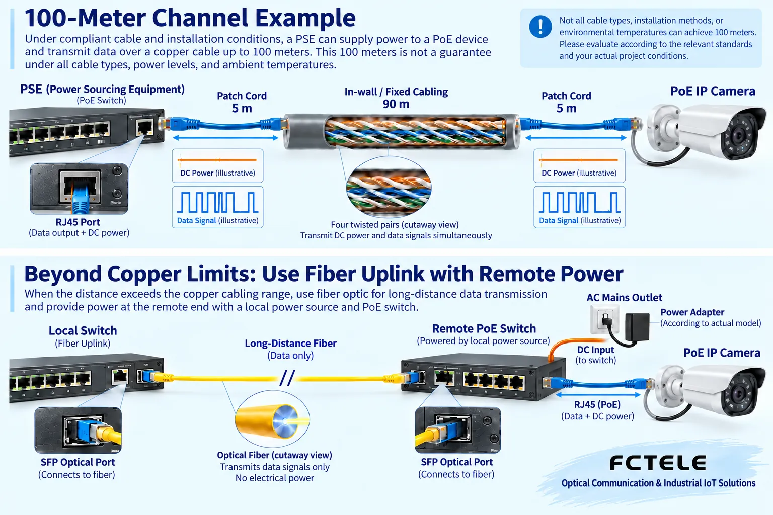
A channel is the complete communication path from the sending device to the receiving device, including permanent wiring, patch cords, and allowed connection points. A common structure example is 90 meters of permanent wiring plus a total of 10 meters of patch cords, for a final total length of 100 meters. You cannot run the permanent cable to 100 meters and then freely add patch cords and multiple adapters at both ends. Special wire gauges, temperatures, or engineering standards may also require stricter length conditions, and the site should be accepted according to the applicable specifications.
Ethernet data travels through twisted pairs as electrical signals that change very quickly, and the receiver must accurately judge them amid noise and attenuation. The longer the cable and the more connectors, the worse the signal conditions may become. The twisted-pair structure helps control mutual interference, but it cannot cancel all loss. Exceeding the applicable length sometimes shows up as link speed reduction, errors, or intermittent operation, rather than necessarily a sudden complete failure at exactly the 101st meter. Being able to connect once does not prove that the link is qualified for the long term.
PoE adds another account: energy is consumed along the way
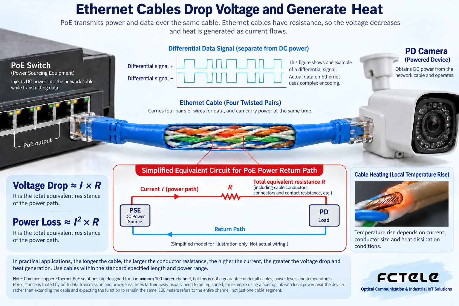
The DC power sent from the power sourcing end passes through copper conductors, and the conductors have resistance, so the voltage and power received at the powered device are reduced. In a simple equivalent model, the voltage drop is approximately current times loop resistance, and the heating loss is approximately current squared times loop resistance. The loop resistance here should include the complete supply and return path being analyzed; you cannot take only one core wire, and you cannot ignore the structure of parallel wire pairs in the standard.
The previously common calculation divided the power difference directly by current, and the resulting unit is not resistance. If estimating resistance from the loss of the same loop, you should use loss divided by current squared, and confirm that the model, current distribution, and parameters all hold. Actual PoE may use different numbers of wire pairs, and ports also have detection and protection conditions, so a simplified formula cannot replace cabling testing or energizing an unknown terminal. The formula helps understand loss; it is not a wiring instruction.
Why does a cable that used to work fail when the load changes?
A camera’s power consumption may differ between day and night, and functions such as fill light and heating can increase demand. The same line may have enough margin at light load, but after the load increases, more obvious voltage drop or heating may occur. The power sourcing end must also simultaneously support the needs of other ports, and insufficient overall device budget can also affect the result. You need to check the port power level, the overall power supply, and the terminal’s worst-case operating conditions at the same time, rather than just measuring the cable length once.
For example, assume a surveillance point is close to the upper design length limit, the image is normal during the day, and it often restarts at night. First record the restart times, PoE logs, and terminal operating status, then check whether they match when the fill light is turned on. If the same load is stable on a short qualified cable, the actual line conditions deserve focused inspection; but you still need to confirm the actual length, terminations, device power configuration, and environment, and you cannot directly declare “the cable is bad” based only on this comparison.
When choosing cable, do not just look at what is printed on the jacket
You should choose qualified copper conductor cable that meets the requirements of the Ethernet speed and PoE type being used, and check the wire gauge, category, environmental suitability, and test data. Materials such as copper-clad aluminum should not be passed off as qualified copper cabling. Names such as Cat 5e or Cat 6 describe the transmission category, not a guarantee for all wire gauges, termination quality, and installation conditions. Likewise, a marketing name such as “oxygen-free copper” cannot replace evidence of standard compliance.
Thin and long patch cords, too many intermediate connections, loose contacts, and crush damage can all cause problems. High power, many cables bundled together, and higher ambient temperatures also require consideration of thermal conditions and specification requirements. RJ45 plugs and modules must match the wire gauge, solid or stranded conductor, and category; you cannot treat “the plug can be crimped on” as qualified contact. Having the cabling personnel perform the corresponding tests and keep records is more reliable than a user judging safety by feeling the cable by hand.
How should the advertised 200-meter-plus mode be understood?
Some specific devices provide a long-distance mode, which may achieve special applications by reducing the link speed or limiting the terminal load. It is not that the 100-meter rule of conventional Gigabit Ethernet automatically stops applying, and it is not that all cameras can get the same power at the same distance. Reading such specifications requires finding the mode, speed, cable requirements, port range, and terminal power conditions at the same time; missing any one item means it cannot be fully evaluated.
Do not plan a critical site based on “someone else can connect at 250 meters.” The wire gauge, supply voltage, terminal power consumption, and temperature of a particular test may differ from your own project. When purchasing, ask the manufacturer to confirm the actual conditions, and during acceptance test the continuous load and environmental changes. If the original equipment does not clearly support it, you cannot infer new distance capability merely through software settings or wiring modifications, and you should certainly not compensate for voltage drop by raising the input voltage of unknown equipment.
For longer links, why is fiber with local power commonly used?
Fiber can carry network data to a farther location, but it does not carry copper PoE energy along with it. A common architecture is that the control room connects to a remote switch via fiber, the remote switch draws power from a suitable local power source, and then uses short copper cable to power the PoE terminal. This separates long-distance data transmission from the final power segment, but you still need to check the modules, loss, power, and environment of both link segments.
The Feichang Technology 4-port electrical 2-port optical managed industrial switch has fiber uplink and PoE optional conditions, and can serve as a product comparison object for this combination. The optical port distance listed on the detail page is not the PoE copper cable power distance, and the input range of the standard version cannot be treated as the condition for the PoE version. Actual ordering requires confirming the optical module, power input, port power, and overall device budget; if there is no suitable power source at the remote end, a separate power design is also needed, and you cannot assume that changing to a fiber cable solves all problems.
Acceptance must measure both data and energy
After installation, record the complete channel length, each connection point, and cable model, and perform applicable cabling tests. Then confirm the powered standard and port allocation, and observe the service and power status under the planned simultaneous load. Conditions such as nighttime fill light, startup, and long-term operation should be included in verification. Inspection of power supplies, grounding, and protective devices should be done by qualified personnel; do not casually disconnect cables, short contacts, or perform probing unsuitable for PoE on energized ports.
The final maintainable result should include “what speed this cable carries, what load it bears, what power type it uses, and what test it is based on to meet the standard.” 100 meters is a starting point to help establish design boundaries, not a universal promise. Understanding that signals attenuate and electrical energy is lost, and then selecting cable and segmenting according to actual conditions, is a truly explainable PoE distance solution.
Verification materials:Cisco PoE cable troubleshooting;TI PoE power specifications;Feichang Technology optical port PoE optional equipment. The principle diagrams are used to explain general mechanisms, not actual measurement diagrams or wiring diagrams for specific models.
Translated from the Chinese technical article. Source first published: 2020-10-29. Source last revised: 2026-10-13T20:37:04+08:00. Read the Chinese source
