


The value of an industrial switch is to maintain verifiable communication capability under selected environmental, power, and network conditions. A metal enclosure, wide-temperature design, and backup path each solve different problems. You cannot infer water resistance, a ten-year lifetime, or a fixed recovery time from the words “industrial-grade.” This article changes the advantage introduction in the old article into a reliability verification method, helping project personnel convert marketing words into actual acceptance conditions.
Reliability must first state where the device is placed and what service it carries
A switch is responsible for sending Ethernet data from terminals to the appropriate ports. Industrial scenarios may have temperature changes, vibration, interference from motor switching, and frequent start-stop power. These conditions affect electronic components, interfaces, and communication links, so industrial design usually needs to consider structure, heat dissipation, protection, and network recovery at the same time. Different models handle different conditions; not all products labeled industrial-grade are suitable for the same environment.
First write down whether the installation location is an indoor cabinet, an outdoor protective box, or inside equipment, state the acceptable interruption range for critical services, and then choose the corresponding specifications. For example, the temperature inside a box may be higher than the outdoor air temperature; the device endures the environment inside the box. A location with condensation also cannot be judged only by the maximum operating temperature. Only after the installation conditions and service goals are clear can you know what needs to be verified.
Wide temperature, heat dissipation, and protection are three different conditions
The operating temperature range indicates the environmental boundary within which the device works under the manufacturer’s specified conditions; it is not equal to the enclosure temperature range. Switch chips and power conversion both generate heat, and the heat must pass through the circuit board, thermal conduction structure, and enclosure to the surrounding air. A fanless structure reduces fan maintenance points, but it still depends on correct installation, heat dissipation spacing, and cabinet ventilation. Do not understand fanless as producing no heat.
If multiple devices are crowded in a closed box, the heat dissipation conditions inside the box change. Even if a single device originally met the wide-temperature specification, the temperature rise should be re-verified. During inspection, record environmental and load changes, rather than judging overheating only by touching the enclosure. Whether ventilation, heating to prevent condensation, or other cabinet measures are needed is determined jointly by the environmental conditions and the manufacturer’s requirements.
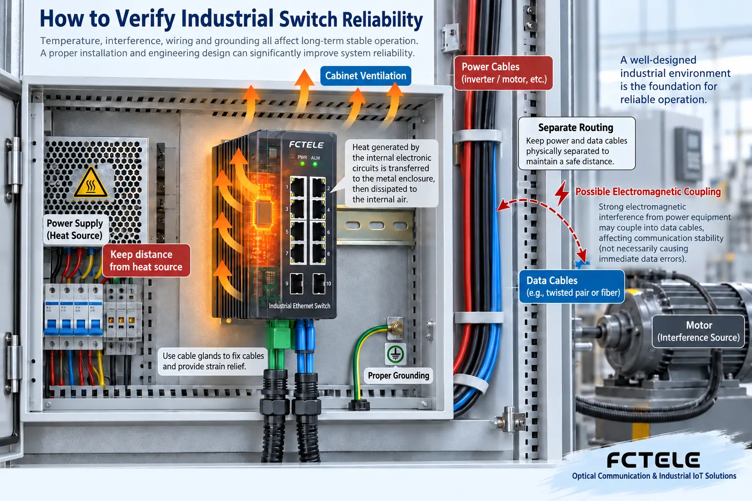
The protection rating mainly describes the enclosure’s protection against the entry of solids and water. It cannot by itself prove corrosion resistance, vibration resistance, or electromagnetic interference resistance. An ordinary DIN-rail switch also cannot be left exposed in a rain area just because its enclosure is metal. If the installation box provides protection, the cable entry holes, connectors, and sealing state after maintenance also need to be verified. The weak point of the entire installation system may not be the switch body itself.
Interference resistance and surge protection depend on test conditions and also on wiring
Electromagnetic compatibility capability is the ability of the device to work under specified interference conditions and to control its impact on surrounding devices. Electrostatic discharge, fast transients, and surges are different tests. Passing one of them cannot be understood as withstanding all impacts. When selecting a model, verify the standards, levels, ports involved, and manufacturer documents. When evidence is lacking, confirm with the supplier rather than inferring certification from the product name.
On site, also check the routing of data cables and power cables, the grounding system, and external protection. When a motor starts and a terminal loses connection, it may come from power fluctuations, interface interference, or cable connection problems. Do not directly conclude that the switch software is broken. Fiber optic links can reduce conductive data paths, but the device still has power and other metal connections, so it does not mean the entire system is immune to lightning strikes. Protective devices and grounding must be coordinated according to the engineering design.
Backup power and backup links solve different fault scopes
Dual power supplies can provide backup conditions for the failure of one power path, but if the upstream shares one power supply or the same protection circuit, they may still fail at the same time. A backup network path responds to a link or node failure in a certain section and cannot replace power redundancy. During inspection, draw the power sources and data topology separately, then ask which devices each fault will affect. Do not combine all “redundancy” into one general promise.
Feichang Technology Managed Industrial DIN-Rail Layer 3 Switch with Four 10G Optical Ports and Eight Gigabit Ethernet Ports The official website information lists dual power inputs, management, and monitoring and maintenance capabilities. These features can provide conditions for designing power supply and maintenance plans. However, the interface combination and management capabilities belong to that product’s information and cannot be generalized to all industrial switches. Specific protocols, protection, and recovery indicators still need to be verified against the delivered model.
Why you cannot accept a ring network with just one millisecond value
Connecting switches into a physical ring does not automatically produce a reliable network. A Layer 2 loop will cause duplicate data to be forwarded in a cycle, and the selected protocol must manage the backup path. In normal operation, a port may block service forwarding while the cable is still connected. After a fault that is allowed to trigger recovery occurs, the protocol reorganizes the forwarding path. Whether it is supported, whether devices are compatible with each other, and what faults are allowed all need to be confirmed according to the device and network design.
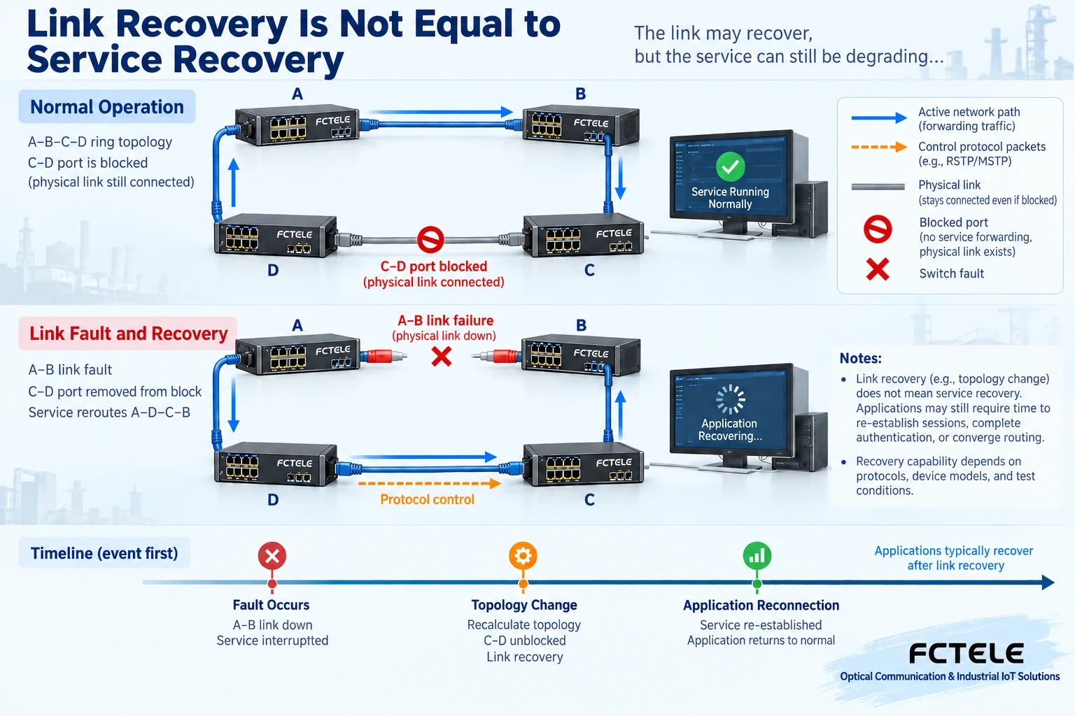
The recovery time given by the manufacturer may be based on a specific number of nodes, traffic, protocol, and fault type. The application may also wait for retransmission, session re-establishment, or the terminal’s own timeout. Therefore, network recovery indicators and the time for PLCs and cameras to actually recover services should be recorded separately. You cannot extend a protocol test result to all industrial switches, nor can you assert that commercial switches are necessarily slower than industrial models.
During acceptance, keep the nodes and protocol configuration consistent, simulate the single point of failure allowed by the design within the agreed window, and record logs, communication interruptions, and application recovery at the same time. Then restore the original path and verify the backup state. Do not disable the loop prevention mechanism just to “test faster,” and do not casually plug connections to form a loop on an unconfirmed production network. Only the test results correspond to the actual conditions of this project.
Lifetime promises should be viewed separately from warranty and repair conditions
The warranty period is an after-sales agreement, design lifetime is a design target under specific conditions, and mean time between failures is a statistical reliability indicator. They are not the same quantity. Even if the document gives a large statistical time, it cannot be understood as every device being able to work continuously for that long. Temperature, power stress, environment, and usage conditions change failure risk. There is no unified lifetime comparison applicable to all industrial models and commercial models.
A more practical question is: can the site specifications be met, how can a fault be located, how can a spare unit and configuration be restored, and can the supplier provide corresponding version documents and repair support. During procurement, verify the warranty boundary, spare parts, and service arrangements. During maintenance, update the port diagram and configuration backup. Together with hardware design, they affect actual downtime losses. You cannot compare only one number for “how many years it can be used.”
Turn reliability requirements into a verifiable delivery checklist
Assume the device is used in a control cabinet near a motor. The project should first record the temperature, power, and grounding conditions inside the cabinet, then verify the selected switch’s range and test documents. After wiring is complete, verify actual communication of critical terminals, and observe error counters and service anomalies under normal load and representative production actions. When redundancy is needed, verify single-path power and allowed network faults separately. Link lights cannot replace service results.
Delivery documents should at least correspond to the device model, version, installation conditions, port diagram, and test results. If a specification is unclear, record it as an item to be verified. Do not use “industrial-grade” to cover gaps. When a fault occurs, still narrow the scope based on evidence. See Power, link, and configuration troubleshooting. This article discusses reliability requirements and boundaries and does not replace a specific model’s installation manual or special certification report.
Documentation basis: The above Feichang Technology product details limit the capabilities of the specific model;Cisco industrial switch REP description is used to verify the blocking path and fault recovery mechanism and is not used as evidence of Feichang Technology protocol indicators. The figures are general structure and mechanism illustrations and do not represent measured performance or product certification.
Translated from the Chinese technical article. Source first published: 2022-06-13. Source last revised: 2026-10-13T20:24:48+08:00. Read the Chinese source
