


A port that does not light up, repeatedly drops offline, or can connect but loses packets does not necessarily mean the switch is damaged. The correct order is to first protect the live business, distinguish physical connection problems from configuration problems, and then verify item by item using known-good cables and the peer device. This article covers how to locate port faults. It does not replace full-network fault analysis, and it does not guide on-site disassembly or repair.
1. How data passes through a copper port
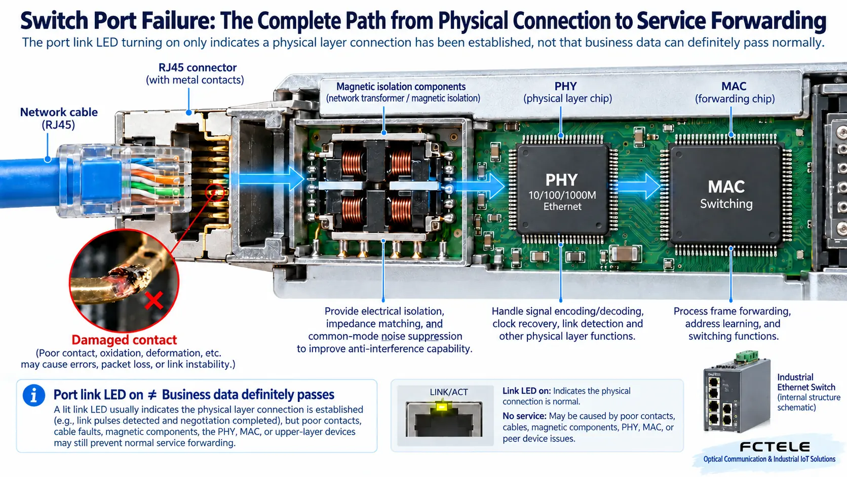
The RJ45 socket is not a simple metal junction box. The twisted pairs in the network cable send differential electrical signals to the contacts, which pass through isolation magnetics into the PHY, the transmit and receive circuit that handles physical-layer signals. It completes link negotiation, signal recovery, and similar work, then hands the data to the MAC interface and switching logic. A loose plug, poor contact in a wire pair, or abnormal interference can all make the physical signal unstable. Even if the outer shell shows no obvious damage, the link can still drop.
The link LED usually indicates that a physical connection has been established, and blinking is often related to transmit and receive activity, but the LED color and pattern are defined by the device manual. A lit LED does not mean VLANs, addresses, or business protocols are correct; an unlit LED also cannot immediately be taken as proof that the chip is burned out. A port shut down by an administrator, a powered-off peer, or an incorrect speed setting can all produce similar symptoms. First record whether the port is “completely unlit,” “periodically blinking off,” or “staying connected but with error frames.” This avoids mixing different problems together.
2. Collect evidence first, then touch the on-site wiring
Record the port number, peer device, cable route, recent changes, and the time when the disconnection occurred. Managed devices can show link status, negotiated speed, duplex mode, and error counters; compare the increase over a period of time rather than only staring at the historical cumulative number. If errors such as CRC continue to increase, check the cable, connection quality, and interference first, but do not judge hardware damage based on a single counter alone. Business timeouts can also come from congestion, the host computer, or protocol parameters.
Before testing, confirm whether the device carries production control, ring network, or PoE power. Unplugging a cable may cut power to a camera or controller, and changing ports may trigger ring network switching. Obtain on-site maintenance permission, prepare a recovery plan, and save the original configuration. Do not arbitrarily short two ports together for testing, and do not disable the security policy of the entire network just to troubleshoot. Do not connect unconfirmed test pens or non-standard power supply devices to a working service port.
3. For copper ports, change only one variable at a time
First check whether the plug is locked in place, whether the cable is squeezed or bent at a sharp angle, and whether there is foreign matter, deformation, or corrosion in the port. An appearance check after disconnecting power also cannot replace electrical testing. Do not put tools into a powered socket. If there is a burning smell, scorch marks, or water ingress, stop using it and hand it to qualified repair personnel; it is not recommended to wipe copper ports directly with alcohol cotton balls, because lint and residue may cause new problems.
During a maintenance window, replace the original cable with a suitable-length, verified-good network cable while keeping the peer and configuration unchanged. If the fault disappears, the original cable or connector deserves further testing; if the problem remains, replace the peer with a known-good one and compare the results again. Only at the end consider changing the switch port, and at the same time match the original port’s VLAN, speed, PoE, and security settings. Being able to use the new port only means the fault scope has been narrowed; you cannot skip configuration differences and declare the old port damaged.
For example, if a camera drops offline every few minutes, you can first record both link events and device restart times. If the camera restarts and the link disconnects along with it, further check the power supply or PoE budget; if the camera does not restart but error frames increase rapidly, focus on checking the line. This example is a diagnostic approach; it does not mean all disconnections can be solved by replacing the network cable alone. Long-distance, outdoor, and high-interference environments also require suitable cabling solutions and protection.
4. For fiber ports, distinguish compatibility, cleaning, and transmit/receive direction
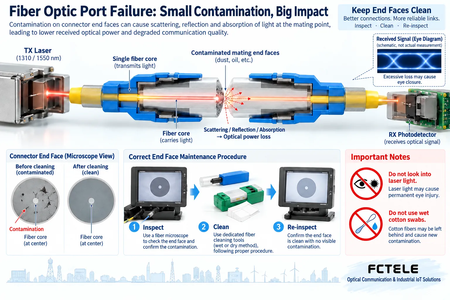
A fiber port link is made up of a transmitter, optical fiber, connectors, and a receiver. Dual-fiber connections usually have local TX connected to peer RX, with the two fibers carrying the two directions separately. Single-fiber BiDi requires a paired complementary transmit and receive wavelength; you cannot just look at whether the plug shape is the same. Speed, fiber type, transmission distance, and the module specifications supported by the device must also match. The specific details are subject to the delivered model and module documentation.
Dust can block or scatter light, reducing the effective optical power reaching the receiver. The correct approach is to inspect the end face with a suitable inspection tool, clean it according to the tool and device requirements, and then inspect again. Do not treat “wiped” as “already clean.” Do not look directly into a fiber port or fiber end face. When replacing a module, confirm whether the device allows hot swapping, pay attention to electrostatic protection, do not touch the end face with your hands, and do not use ordinary tissue instead of dedicated cleaning tools.
5. Accept port results separately from configuration results
After the physical link is stable, continue to check VLANs, addresses, access policies, and application communication to avoid stopping just because “the LED is on.” For services that need continuous operation, observe a time window appropriate to the on-site load and check whether there are still link re-establishments, growing error counters, or business timeouts. Restore the original monitoring and security configuration, record the cables, modules, and ports that were replaced, and leave reproducible evidence.
The Feichang Technology official website lists features such as port statistics, logs, Ping, and port mirroring for managed switches. Statistics and logs can help locate the time point, and mirroring can send specified traffic to an analysis device; these capabilities do not mean the device automatically repairs faults, and not every model has them. If the mirror port speed and capture device capacity are insufficient, packets may be missed. Before use, check the currently delivered version and permissions.
When the same physical port, under the same configuration, still remains abnormal after cross-verification with a normal cable, a normal peer, and a compatible module, and configuration and environmental factors have been ruled out, only then is there stronger evidence of a hardware fault. At this point, save the logs and test records and contact technical service. Do not weld or modify the port yourself. The reminders about hot swapping, cable stress, and outdoor surges in the original text can be retained, but they should be implemented as prevention and inspection items, not as untested damage conclusions.
References:Fluke Networks fiber inspection and cleaning materials;Feichang Technology managed switch product details. The principle diagrams are general mechanism illustrations and do not represent actual objects, measured data, or model commitments.
Translated from the Chinese technical article. Source first published: 2021-01-15. Source last revised: 2026-10-13T17:34:48+08:00. Read the Chinese source
