


When pairing a managed industrial switch with a Ethernet fiber media converter, the first thing to match is the Ethernet interface and the optical link, not making two devices have the same network management menu. A transceiver converts electrical signals and optical signals into each other, allowing existing Ethernet services to be transmitted over fiber; it usually is not responsible for understanding service protocols on behalf of the terminal, and it will not automatically become a remotely manageable device just because it is connected to a managed switch.
1. First look at which type of interface you are actually missing
If the switch has an optical module slot that supports the target specification, you may be able to directly insert a suitable module to connect to fiber; if it only has copper network ports, you can convert the medium through an external fiber optic transceiver. The former requires checking compatibility between the slot and the module, while the latter also adds an independent device, power supply, and maintenance location, so you cannot just compare which connection cable is shorter.
SFP is a module form factor, while LC, SC, ST, and others are optical connector form factors; they answer different questions. LC does not equal single-mode, and 100BASE-FX cannot be judged as a fiber type based only on the interface shape. The fact that the same connector can be plugged in only means that some mechanical conditions match; it does not prove compatibility of speed, wavelength, optical power, or encoding.
2. Understand one complete electrical-to-optical conversion
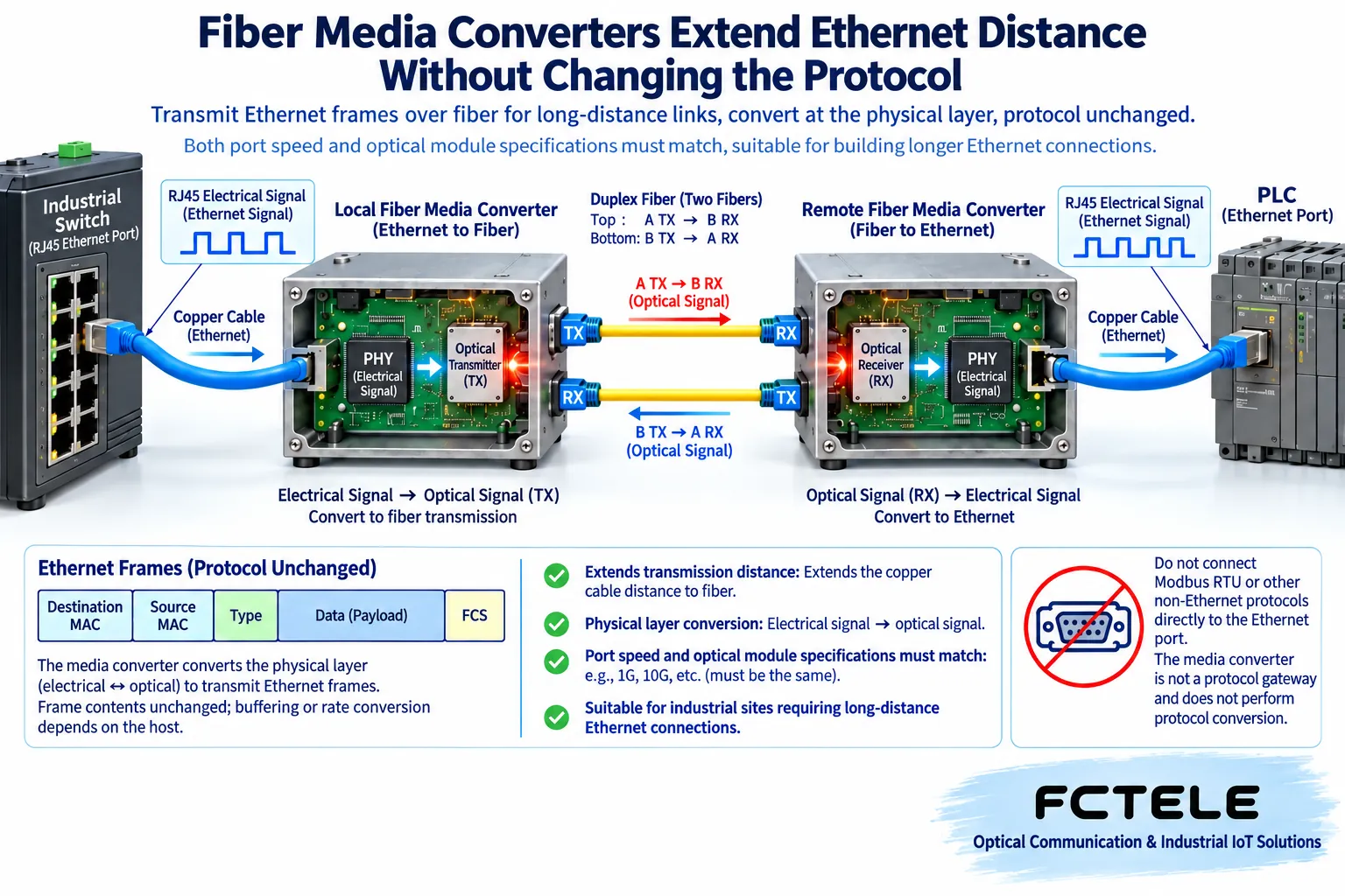
The industrial switch sends an electrical signal through the copper port. The transceiver’s Ethernet physical layer circuit receives and processes the signal, and then the optical transmit section turns the corresponding data into an optical signal. The remote optical detector turns the light back into an electrical signal, which is sent through the corresponding circuit to the remote copper network port. Specific products may use different internal schemes, but the Ethernet methods supported by each interface must match each other.
This is not putting a complete video image into the fiber, but transmitting the signal that carries the service. It is also not a universal protocol converter: when a PLC already uses Ethernet services such as Modbus TCP, media conversion can become part of the link; a device with only an RS485 interface and Modbus RTU output cannot directly gain TCP protocol conversion capability through an ordinary Ethernet transceiver, and it needs a corresponding gateway or serial-to-network device.
3. Copper port auto-adaptation does not mean the optical port can auto-adapt to anything
When a product says the copper port supports multiple speeds, it does not mean the optical port also supports all the same speeds. One device may accept 100 Mbps service on the copper side and then connect to a matched remote end over a fixed Gigabit optical link; another device may require both sides to use a specific speed. You need to look at the copper-side and optical-side descriptions separately, and not directly pair two optical ports just because they are both Ethernet.
In addition to the nominal speed, you also need to check duplex mode, negotiation behavior, maximum frame length, and whether VLAN tag pass-through is supported. When the uplink needs to transmit tagged frames, if the transceiver changes or discards tags, logical grouping may become abnormal; when using larger service frames, the capability of the entire path should also be verified. One device supporting jumbo frames does not mean the terminal, switch, and other links all support them.
4. Look at fiber count, wavelength, and power together
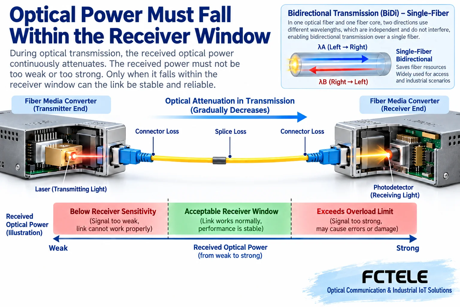
In the dual-fiber method, one fiber is usually used for one direction and the other for the reverse direction, and the transmitting end TX must connect to the remote RX. In the single-fiber bidirectional method, different wavelengths are used on the same fiber core to distinguish the two directions. A common pairing is that the local transmit wavelength corresponds to the remote receive wavelength, and the local receive wavelength corresponds to the remote transmit wavelength. Two devices both marked as A-end may not necessarily form a correct pair.
Single-mode and multimode are classifications of optical fiber and propagation conditions, and they do not correspond one-to-one with connector shapes. You should also check the actual installed fiber type, connectors, patch cords, and device optical specifications. The distance grade on the nameplate is only an option under specific conditions and cannot be directly treated as a distance already guaranteed on site; connectors, splices, and aging loss along the way must all be included in the calculation.
The received optical power must fall within the window allowed by the device. If it is too weak, it may not be received correctly; if it is too strong, it may also exceed the receiver’s overload boundary. A rough budget is transmit power minus optical path loss, then compared with the remote receive range, with a reasonable margin reserved. Specific values come from the corresponding module data and on-site measurements, and you should not replace them with one set of “universal power” values for the entire transceiver category.
5. Network management is another capability that must be verified separately
An ordinary transceiver can transmit compatible Ethernet services with a managed switch, and it does not necessarily have to support SNMP. SNMP is a management information exchange protocol. The management station reads or sets status through the device’s management agent and the corresponding information definitions. The same protocol name does not mean that a certain switch can automatically manage all third-party transceivers.
Remote OAM and other operation and maintenance functions may also require specially matched remote devices. Feichang’s official website lists Console, Web, and SNMP management methods for its managed industrial Gigabit 1-fiber-1-copper transceiver, and explains remote management applications with matched plug-in card devices. This type of capability is suitable for remote maintenance needs, but you should check the specific version, matching relationship, and statuses that can be read, and not confuse ordinary optical link interoperability with remote network management compatibility.
6. Power supply and fault behavior determine whether the site is easy to maintain
Fiber does not transmit ordinary DC power. The remote transceiver and terminal each need a clearly defined power supply plan. When a certain device provides PoE, you need to check whether it is the power sourcing equipment or the powered device, as well as the standard, power, and budget; you cannot assume that the remote device automatically gets power just because the transceiver is connected to a switch.
You also need to see how the copper port behaves when the optical path is broken. Some devices can let the remote end sense the disconnection through link fault pass-through, while others retain the local copper port link light. A port light being on does not prove that the remote service is still reachable. Alarms, power failure detection, and recovery behavior must be tested, and power supply faults, fiber faults, and terminal failure to respond should be recorded separately.
7. First do a short link, then extend to the actual optical path
First use a known-good short patch cord to establish a baseline for a pair of devices, confirm bidirectional communication, copper port negotiation, tags, and the actual service, and then add the on-site fiber. Follow safety procedures to check connector cleanliness and bending, use a matching optical power meter, and do not look directly into optical ports or use your eyes to find light. Change only one condition at a time, so that if an abnormality is found there is a comparable basis.
The handover record should at least include the models at both ends, module or fixed optical port specifications, fiber type and direction, power supply, firmware, received power, and continuous service results. On-site temperature, installation, and grounding should also be checked according to their respective models. Choosing the right transceiver is not finding a pair of boxes with the same plugs, but making sure every interface, signal, and maintenance path has evidence to support it.
References:Feichang managed transceiver product list,1-fiber-1-copper Gigabit transceiver details,Fiber connection and interface safety instructions. The illustrations are general principle diagrams, not actual Feichang models or measured optical power.
Translated from the Chinese technical article. Source first published: 2023-11-21. Source last revised: 2026-10-13T17:37:33+08:00. Read the Chinese source
