


When there is only one Ethernet point at the site that needs to cross fiber, and when multiple devices need to be connected centrally, these are two different tasks. The former can consider a suitable media conversion device, while the latter often needs a multiport switch. But the name “Ethernet fiber optic transmission device” may refer to a fiber optic transmission device or to a dedicated-line Ethernet bridge, so you cannot order just by the name. First confirm what kind of service the device carries and how ports forward between each other, then check bandwidth and management functions.
First look at the service port, and do not interpret Ethernet as analog video
What an Ethernet terminal sends is data frames organized according to Ethernet rules. A frame contains information such as source and destination MAC addresses; MAC addresses are used for link-layer identification. Twisted pair and fiber can carry this kind of service, but the electrical interface, optical port rate, and encoding must match. Analog video fiber optic transmission devices, SDI fiber optic transmission devices, and Ethernet media converters are not the same kind of device. Even if they all have fiber connectors on the housing, they cannot be directly substituted for one another.
RJ45 is likewise only a clue about connector shape; some devices use it to carry serial ports or other services. Check the port description and electrical definition, and do not plug every RJ45 into a switch. Industrial Ethernet is also not a unified “2-wire half-duplex” system; the actual twisted-pair interface, negotiation method, and operating rate should be checked against the corresponding Ethernet standard and product documentation, and the description of an RS485 bus cannot be carried over.
Media conversion changes the transmission medium, but the service is still Ethernet
A common one-copper-one-fiber transceiver sends the Ethernet service received at the copper port to the optical port, and then the remote device restores it to a copper port. Inside there are corresponding physical interface circuits and optical transceiver components; it may include buffering and bridging processing, so you cannot generally say that all transceivers “only change levels and do not process frames.” Whether a specific model learns MAC addresses, filters frames, converts rates, or supports management must be checked by model number.
This kind of device mainly solves the transmission distance or medium connection problem of one point, and it does not gain more terminal interfaces just because the fiber becomes longer. If the site needs to connect multiple instruments or network cameras, port aggregation still needs to be planned. When a device has two electrical ports, you must also ask clearly about port sharing, isolation, and uplink relationships, and you cannot infer that it is equivalent to any switch just from the number of ports.
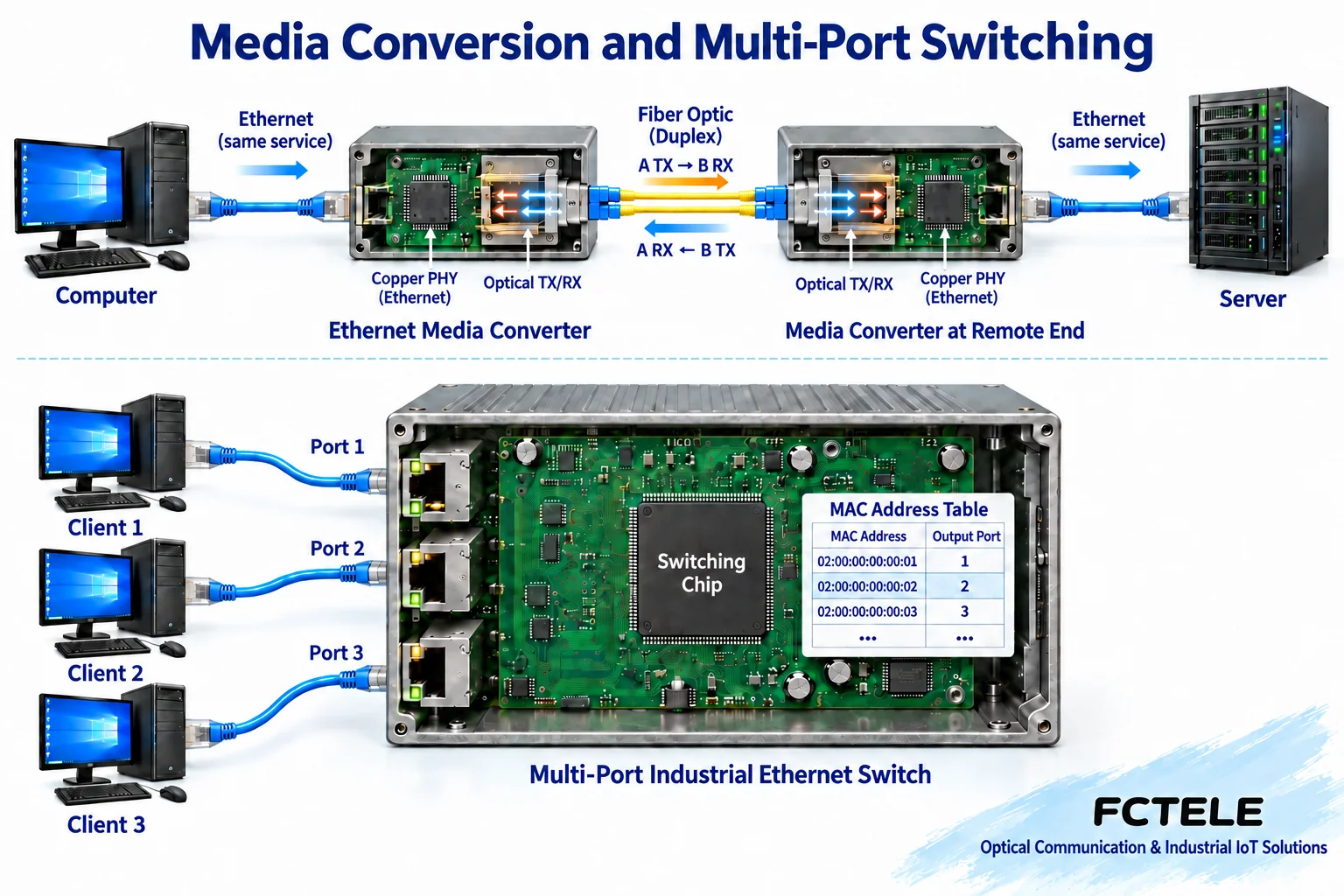
How does a switch decide which port to send from?
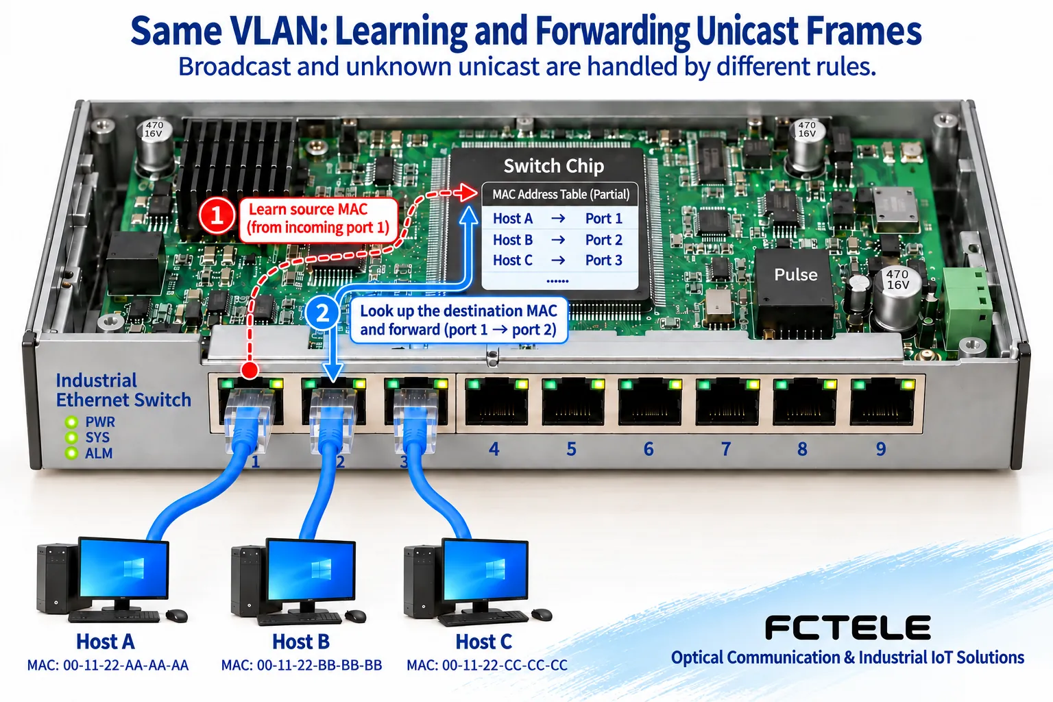
Within the same VLAN, a switch usually learns which port a device is on based on the source MAC address of received frames, and then looks up the destination MAC address. If the destination port is already known, it sends the known unicast frame to the corresponding exit according to the forwarding rules. Broadcast or unknown unicast has different handling rules, so you cannot say that a switch always sends to only one port. A VLAN is a mechanism for dividing Layer 2 broadcast domains, and it is not equal to physically splitting into completely independent devices.
When different devices send data to a slower uplink at the same time, queuing and congestion can still occur. A full-duplex link reduces the traditional shared-medium collision problem, but it does not eliminate the exit capacity limit. Port rate, switching capacity, buffer, service bursts, and QoS policy should all be checked against requirements. If crossing IP subnets is required, routing functions are usually also needed; a switch with Layer 3 functions can take on part of the routing task according to configuration, and you cannot limit all switches to exactly the same capabilities.
“100M network port” does not guarantee that the entire dedicated line has 100M bandwidth
Feichang Technology FCP-F Ethernet optical modem The page marks the product as having 2M bandwidth, while also listing a 10/100M Ethernet interface and self-learning Ethernet bridge function. It is aimed at specific dedicated-line extension and device combinations, and you cannot assume that the net service across the line also reaches 100M just because the computer’s network card negotiates to 100M. The interface negotiation rate and the actual bearer channel capacity are two different numbers; testing should observe end-to-end throughput and drops, not just the network card status.
Feichang Technology B series 1-port gigabit Ethernet fiber media converter This belongs to the Ethernet media conversion product category, and the page lists fiber configuration and Ethernet functions. Both names contain “optical,” but their uses and capability boundaries are still different. The distance, power supply, and temperature listed on the web page include different options, so a complete configuration should be obtained when ordering, and you cannot apply the maximum distance in the series or some power supply capability to every device.
Choose by two site examples, not by box size
Suppose the remote end has only one IP camera and the center already has network receiving capability; you can first compare a one-copper-one-fiber transceiver with a small optical-port switch. Besides the optical link, you also need to consider camera power, environment, management, and maintenance requirements. You cannot assume that the transceiver provides PoE, nor can you assume that a switch with optical ports supports all optical modules. If the camera outputs SDI, you should return to the corresponding video transmission solution rather than trying to replace it with twisted-pair equipment.
If the remote end has multiple IP cameras and controllers, switch aggregation makes it easier to organize ports, but the uplink capacity must cover the actual service. When multiple gigabit electrical ports share one uplink, it does not mean that every terminal can simultaneously monopolize the full uplink bandwidth. VLANs, multicast, and loop protection should also be planned; the existence of a function does not mean it has been correctly configured. Do not temporarily interconnect multiple ports repeatedly for testing in a way that creates a loop.
For acceptance, check layer by layer along the terminal, copper port, optical link, and forwarding
First use a known-good terminal and a short link to verify the service, then connect the target device and optical link, and record the interfaces at both ends, rate, duplex, optical port configuration, and test load. At the optical layer, check fiber type, single-fiber or dual-fiber, wavelength pairing, loss, and receive range; a long-distance optical port may also be overloaded when tested with a short fiber, so necessary attenuation should be applied according to specifications. If the device supports functions such as link fault pass-through, also confirm the current settings and behavior at both ends, and do not just look at whether the light is on.
If the link is normal but the service does not work, continue checking VLAN, MAC learning, addresses, and the protocol path; if it stutters after the load rises, observe the increments in errors and drops to distinguish link problems from exit congestion. Change only one condition at a time, and operate within an approved test window. Finally, keep the configuration and test records so that the reason for choosing “conversion” or “switching” can be reviewed.
Reference for the roles of switching and routing Cisco routing explanation; general mechanisms do not prove that any Feichang Technology model has all functions.
Translated from the Chinese technical article. Source first published: 2020-11-27. Source last revised: 2026-10-13T18:44:52+08:00. Read the Chinese source
