


Single-mode and multimode refer to the propagation modes of light in fiber, not how many video channels a fiber optic transmission device can carry, and not single fiber versus dual fiber. When selecting a model, you need to check the service interface, the device’s optical port, the fiber category, the rate, and the actual loss together. Multimode can carry high-speed short-distance links, and single-mode will not automatically speed up a service that was originally low-speed; “multimode is definitely low-speed, single-mode is definitely more expensive” cannot be used as a purchasing rule.
1. First separate three easily confused terms
One device can be single-mode, single-fiber bidirectional, and a multi-service fiber optic transmission device at the same time. Single-mode answers how light propagates in the fiber core; single-fiber answers how many physical fiber cores are occupied; multi-service answers which interfaces are carried, such as video, serial port, telephone, or others. The three describe different dimensions, and there is no corresponding relationship that “single-mode can only carry one channel, multimode can carry multiple channels.” The requirement list should list each dimension separately, and you cannot just write “buy a multimode fiber optic transmission device.”
The optical signal is also not a picture moving through the fiber core. The transmitting circuit completes sampling, encoding, or multiplexing according to the service, and drives the light-emitting device; the receiver converts changes in optical power back into electrical signals, and then restores the corresponding interface. Single-mode and multimode affect the intermediate optical propagation conditions. Whether the input end is CVBS video, E1, or Ethernet is still determined by the specific product.
2. Why multiple propagation modes broaden pulses
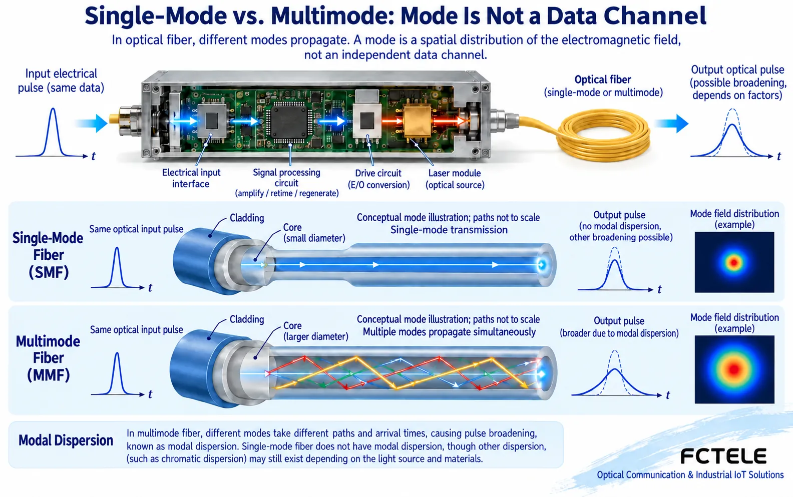
An optical fiber consists of a core and cladding. Modes can initially be understood as different electromagnetic field distributions that satisfy propagation conditions. The different paths in the figure are only simplified drawings to aid understanding. A multimode fiber core allows multiple modes to propagate, and they may arrive at the receiving end at different times. A narrow pulse sent at one moment may be stretched wider in time after passing through the link. This is an intuitive manifestation of mode dispersion.
When the symbol interval is relatively wide, the receiver may still be able to distinguish adjacent symbols; at higher rates or longer distances, broadened pulses are more likely to affect each other. You cannot only measure how strong the optical power is; you also need to confirm whether the waveform and timing meet the interface requirements. Specific limits are related to fiber grade, launch conditions, wavelength, and equipment standards. There is no unified kilometer number that applies to all multimode equipment.
3. Why single-mode suits many long-distance solutions
Under specified wavelengths and operating conditions, single-mode fiber mainly supports fundamental mode propagation, avoiding arrival time differences between multiple modes. However, it may still be limited by chromatic dispersion, loss, bending, and connection quality. “Single-mode can go infinitely far” is not true. The device’s transmit power, receive capability, and supported transmission format also have boundaries. Increasing transmit power cannot infinitely compensate for all problems.
When comparing core diameters, distinguish the fiber core from the entire fiber. Common multimode core specifications include 50 or 62.5 micrometers, and common single-mode cores are on the order of several micrometers to ten micrometers; these are category descriptions and are not used to judge the on-site fiber core by eye. Actual confirmation should check the cable markings, project completion documents, and test records, and you cannot rely only on the color of the patch cord jacket.
4. First confirm the existing fiber, then check the optical port version
When there is existing multimode cable in a building, first check its grade, length, connectors, and end-face condition, then check whether the target device clearly supports that fiber and the target service rate. You cannot connect a single-mode device to a multimode patch cord and conclude that the entire link is compatible just because the light turns on over a short distance. Some standards have specific mode conditioning or mixing conditions, but there must be a clear standard and model basis. Special solutions cannot be treated as permission to mix freely.
For a newly built cross-plant link, evaluate distance, margin, future expansion, maintenance inventory, and cabling cost together. When both solutions meet the service, compare the complete project cost, not just the selling price of one device. Optical port options, replacing the opposite end, test tools, and fault maintenance also generate costs; you cannot continue to use the old conclusion that “single-mode is always expensive, multimode is always cheap.”
5. Power budget is another independent check
Link budget represents the margin between the allowed loss at the transmitting end and the receiving end. Fiber attenuation, connectors, splice points, splitters or wavelength division devices, and maintenance margin should all be included in the calculation. Received optical power uses dBm, and loss uses dB; the two cannot be mixed up. The receiver has both a sensitivity lower limit and possibly an overload upper limit; when connecting high-power long-distance equipment over a short distance, you also need to check the receive range.
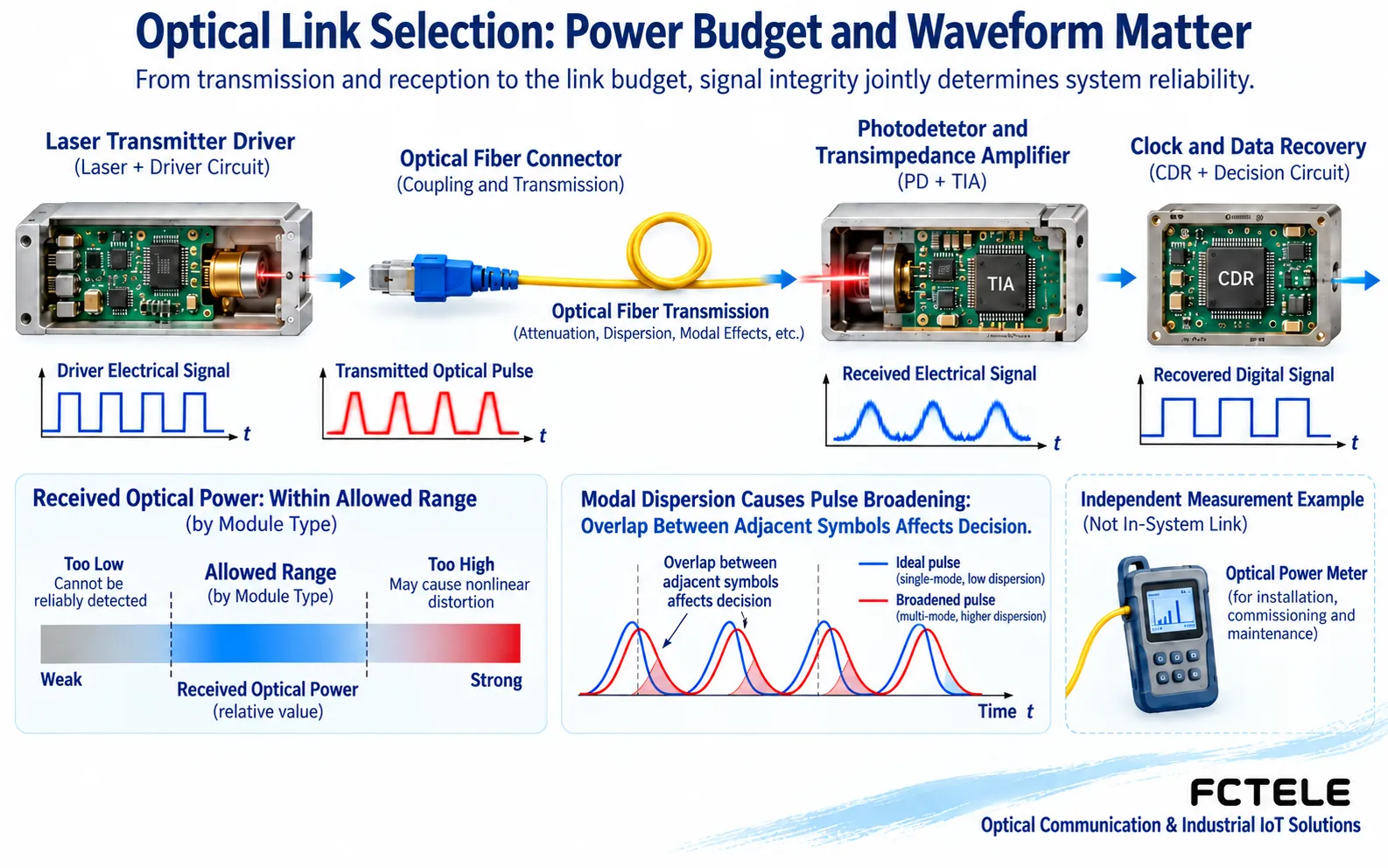
Passing the power check cannot directly prove that the service passes. The receiver may have light but still be unable to recover correct data. Reasons include incompatible format, rate mismatch, waveform degradation, or service configuration errors. Reference Cisco fiber propagation and dispersion materials to understand the mechanism, then complete acceptance according to your own model documentation, and do not copy other manufacturers’ thresholds.
6. Complete selection with one reproducible test
First test the actual service on a known-good short link with matching specifications, keep the input, output, error counts, and device version, then connect to the formal cable. When there is an abnormality, replace only one factor at a time to distinguish a service interface error from an optical link problem. Verify all channels, both directions, and continuous operation. You cannot make a delivery conclusion based only on one power-up and one indicator light.
Feichang Technology 4-channel integrated multiplexed video fiber optic transmission device is a product example selected according to service configuration. When choosing this type of device, first determine the video and additional service combination, then check with the manufacturer about the single-mode or multimode optical port option, paired end, and optical budget; you cannot generalize one version’s distance or wavelength to all fiber optic transmission devices. Use dedicated tools to clean end faces and inspect first, and do not look directly into the optical port; schedule fiber removal measurements for production links during a maintenance window.
Documentation note: The images are general principle illustrations, not teardown, actual measurement, or certification of a specific product. Specifications are subject to the actual model, firmware, and engineering tests.
Translated from the Chinese technical article. Source first published: 2024-02-29. Source last revised: 2026-10-13T17:09:56+08:00. Read the Chinese source
