


The advantage of a card-based fiber optic transmission device is that it organizes service cards and installation space, but “card-based” does not automatically mean service aggregation, unlimited expansion, or hot swapping. First distinguish a centralized-power chassis from a modular platform with service multiplexing capability, then check slots, power, optical links, and remote-end matching to know what expansion actually changes.
1. What problems does the chassis solve?
Multiple standalone desktop devices take up space, scatter power supplies, and increase cabling management difficulty. A card-based chassis allows cards to be installed centrally, using the corresponding power supply and fixed connection structure, which makes numbering and maintenance easier. However, putting devices in the same box does not mean the data naturally combines into one link. The internal backplane may only distribute power, or it may carry management or service data; the specific architecture determines what it can do.
Before buying, ask four things: which cards the chassis supports, whether each card has its own optical port, what signal the backplane carries, and how the remote end is matched. Knowing only how many empty slots there are, without knowing these conditions, makes it impossible to judge expansion capability. Even if card sizes from different manufacturers look similar, they should not be mixed across brands at will; connectors, power, and backplane definitions may differ.
2. Centralized power does not equal shared service bandwidth
One common structure is a common power supply feeding multiple independent optical multiplexer cards, while each card’s service processing and optical channel remain independent. The first card pairs with its remote end, and the second card pairs with another remote end. Adding a card usually requires adding the corresponding fiber, remote device, and service interface. The common power line is not a data aggregation channel, so you cannot say that simply plugging into the chassis automatically turns multiple video channels into one network uplink.
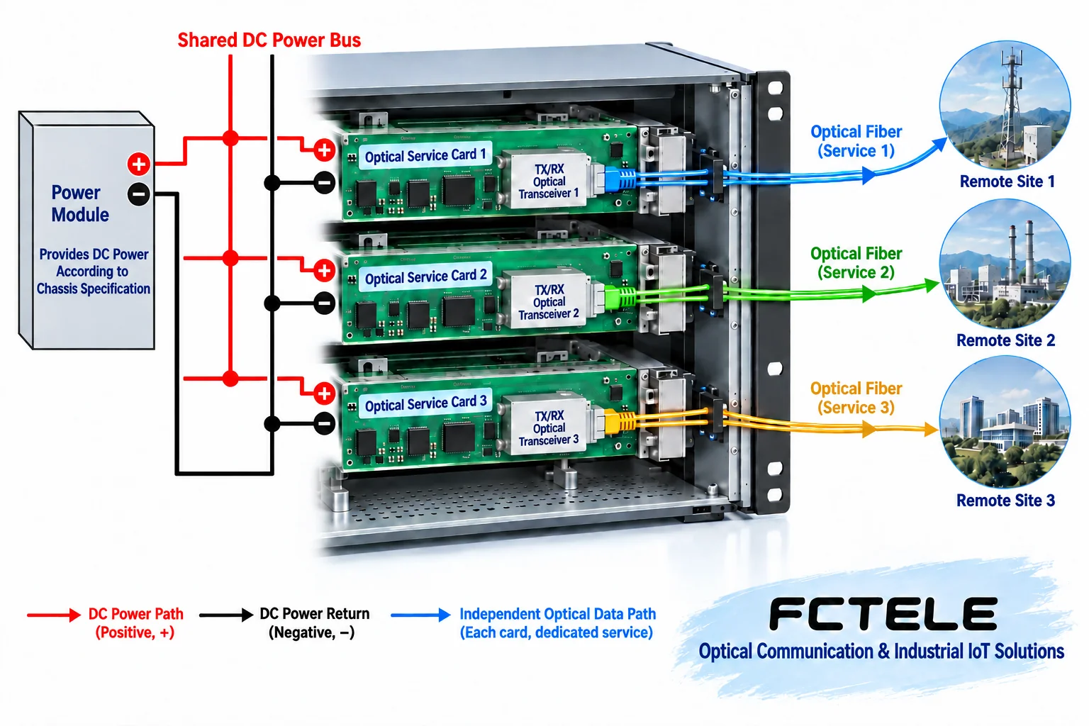
This structure makes centralized installation easier, but the common part can also become a shared point of impact. An abnormality in a single service card may affect only the corresponding service; a common power failure may affect multiple cards. Whether there is redundant power, how faults are isolated, and whether alarms can be traced to a card must all be verified for the specific product. You cannot further infer from “each card transmits independently” that “any single point of failure will not affect other cards.”
3. How a service multiplexing platform shares transmission
Another type of modular platform multiplexes multiple services inside the device according to a clear mechanism. Taking time-division multiplexing (TDM) as an example, voice is sampled and encoded into digital samples, and different services occupy their own time positions in the transmission frame. The receiving end separates the samples according to the agreed positions and delivers them to the corresponding interfaces. It is like multiple windows using one conveyor belt in a fixed order; both the order and the capacity must be designed in advance, rather than just connecting wires together randomly.

Shared transmission means total capacity and service allocation need to be checked. Having empty slots does not mean the remaining optical link capacity can accommodate any combination of cards; the receiving end must also be able to recognize the corresponding service. TDM multiplexing and Ethernet packet forwarding are not the same mechanism, and the same set of “network port rates” cannot explain all multi-service platforms. Some systems also provide network interfaces, but network functions and the organization of traditional services should be verified separately.
The Feichang FC2PM-O64/S64 details list service card slots and module options, which can serve as a reference for checking platform combinations. The specific supported services, network interface versions, management options, and configurations at both ends should be confirmed at the time of ordering. This reflects the selectability of modularity, but it does not mean that all options listed on the webpage will appear simultaneously in every device.
4. For expansion, calculate capacity first, then confirm compatibility
First list the existing channels and new channels, stating what interfaces and directions are needed for video, telephone, serial, or network services, then check the chassis slots, total power consumption, heat dissipation, transmission resources, and remote-end capabilities. Power ratings cannot simply be pieced together from single-card power consumption; the manufacturer’s combination and margin requirements must also be followed. Heat dissipation conditions in a high-temperature cabinet must also meet the design, and the fact that the chassis still has empty slots does not prove that the load conditions are acceptable.
Card compatibility may also involve hardware versions, firmware, and management modules. Maintenance personnel should save the original configuration and card position information, and confirm the corresponding remote end and optical port conditions before adding new cards. If the platform allows full configuration, use it according to the specified combination, and do not broadly require all chassis to leave one empty slot; if a certain combination is not allowed, do not force its use just because it physically fits.
5. Redundancy and hot swapping must be checked separately
Redundant power supplies are used to improve power availability, backup optical links are used for corresponding transmission protection, and hot swapping involves the electrical sequence, surge control, and system processing capability during insertion and removal. These three functions are related but do not prove one another. If a product says dual power supplies, you cannot infer that service cards can be removed while powered; if it says optical path backup, you cannot infer that any fault will cause no interruption or require no reconfiguration.
Replacing cards must follow the device manual and shutdown procedures. Production services need a maintenance window and a recovery plan; cards must not be suddenly pulled out just for demonstration convenience. If a certain type of hot swapping is explicitly supported, it must still be operated according to the rules, and the scope of impact and recovery status must be confirmed. This article does not provide live-operation steps for unknown models, because when interface definitions and safety conditions are unclear, generalized steps may cause damage.
6. Validate with a hypothetical expansion scenario
Suppose a campus adds two groups of remote telephones. To determine whether the existing platform can be expanded, first check the service cards, telephone interface roles, transmission resources, and remote-end combination. If it is only a centralized-power chassis, the addition may still require independent optical links; if it is a modular platform supporting the corresponding multiplexing, then service allocation and remote-end configuration must be confirmed. Both architectures may meet the need, but wiring and capacity judgments cannot be mixed. This is a teaching hypothesis, not a Feichang customer achievement.
During acceptance, test both the new services and retest the original services, confirming channel correspondence, power alarms, necessary protection switching, and management records. Delivery documents should save each card’s model, slot position, remote end, and parameters, and clearly state shared resources and the scope of fault impact. The real value of card-based equipment is making expansion more manageable under clear compatibility and capacity conditions, not interpreting “flexibility” as having no boundaries.
Reference Feichang modular product category and multi-service optical multiplexer details. The illustrations are schematic diagrams of architecture and multiplexing principles, and do not represent internal photos of a specific chassis, permission for live operation, or measured performance.
Translated from the Chinese technical article. Source first published: 2024-10-09. Source last revised: 2026-10-13T17:37:33+08:00. Read the Chinese source
