


An optical LED on with copper off, unequal endpoint LEDs or normal LEDs with failed service cannot diagnose broken hardware from a universal chart. Divide power, copper, optics and service, using model definitions and fault propagation as evidence. This article concerns point-to-point Ethernet converters, not ONU PON-registration or telephone indicators.
1. Map the path before choosing a segment
A typical path runs from device 1 through copper to A, fiber to B and copper to device 2. Both converters handle two directions. Copper PHYs detect links, optics convert signals and some products forward/buffer frames. LEDs show only part of this and cannot replace full-path measurements.
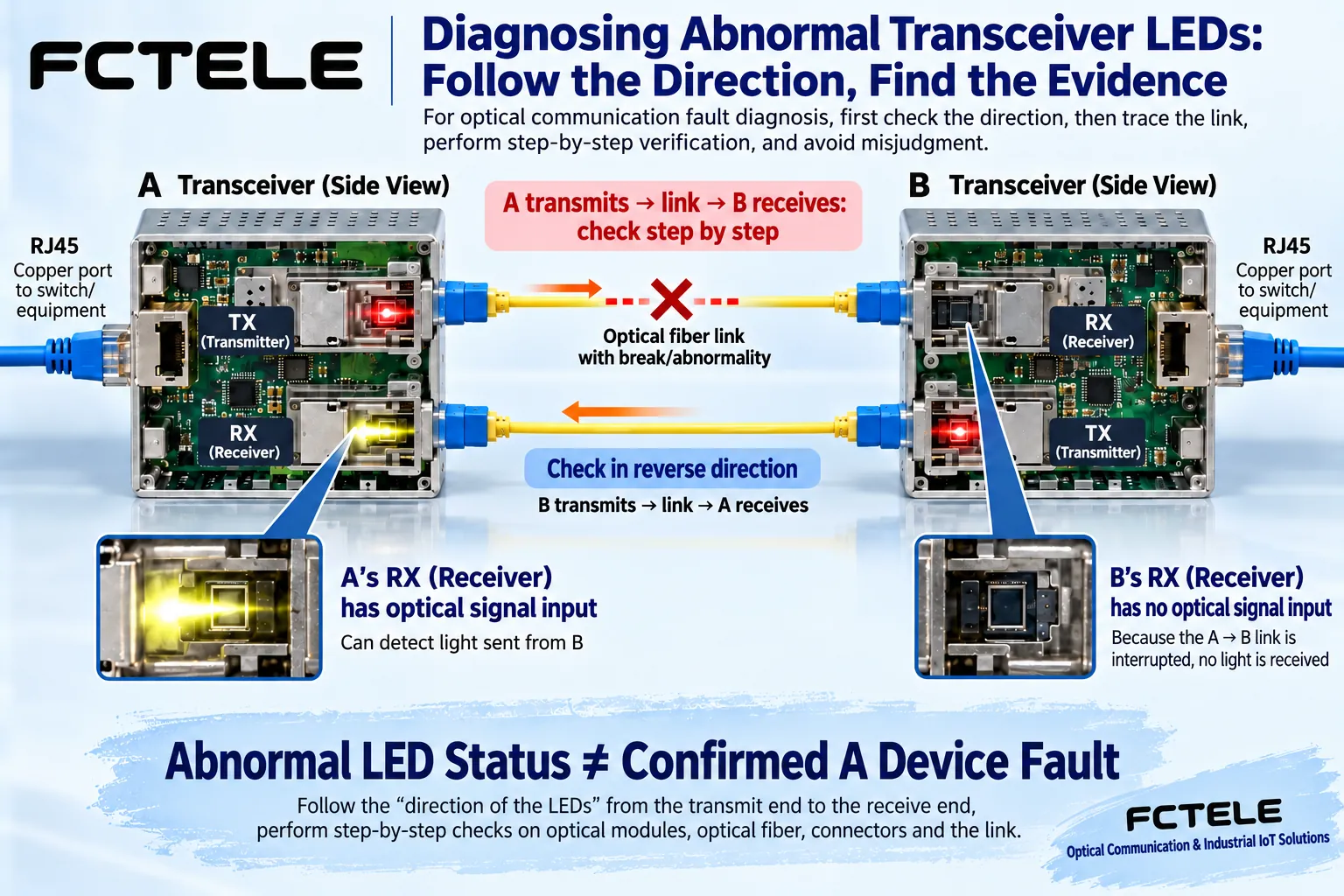
Record models, power, optics, copper/fiber locations and every LED name/state. Trace duplex TX to opposite RX in each direction. For single fiber, check complementary wavelengths rather than swapping a nonexistent second core. Photograph unclear markings and consult manuals; a TX copper-status label is not necessarily an optical-transmitter indicator.
2. Isolate power problems first
If endpoint PWR LEDs are off or fluctuating, check actual power, adapter specifications and seating. Local power cannot prove remote power. A lit PWR cannot prove stability under load changes. Competent personnel should follow equipment/instrument procedures, not calculate voltage from LED color/brightness or substitute arbitrary adapters.
Ordinary users should disconnect before checking connections/nameplates and avoid opening mains supplies or live devices. Stop energizing burned, damaged or wet units and contact maintenance. Repeated cycling may temporarily recover but lose clues. Save LEDs, logs and timing before necessary approved-window actions.
3. With no optical link, check specifications and end faces before power
Check rate, mode, wavelength and connectors with both endpoints powered. Trace duplex directions or complementary BiDi endpoints. Dirt, loose connectors, bends and damage affect reception. Never look into ports or use sunlight, flashlights or ordinary laser pointers to judge the line.
Set a power meter to the operating wavelength and measure the relevant receive direction against exact sensitivity/overload specifications. One set of negative thresholds is not universal. A visible fault locator is a specialized safety-controlled aid for some breaks/bends, not a replacement for working-wavelength loss tests or proof of application operation.
If A optical status is on and B off, the failed direction may involve A transmission, the path, specifications or B reception; detection logic also matters. Substitute one known-good compatible jumper as a controlled test. Simultaneous replacements cannot establish cause. Compare before/after results.
4. With copper off, include peers and fault propagation
Check peer power, cable seating, disabled ports and negotiation. Continuity tests identify some wiring problems but cannot certify high-frequency cabling. Use suitable certification tools/models where required. Unexpected fallback calls for pair, termination, peer and configuration checks. Optical reach cannot guarantee copper performance.
Older equipment may need straight/crossover cabling or manual modes; newer equipment may adapt. Old To HUB, To Node or switch positions cannot define every panel. The FCTEL Gigabit B-series lists automatic crossover for applicable versions, but actual port behavior still follows its manual.
5. LFP makes remote faults visible and LEDs interdependent
Link Fault Pass-through propagates a failure indication to another side. A model may alarm or change a related link state. It neither repairs fiber nor universally provides redundant switching. Distinguish the original failure from later effects so one broken link is not mistaken for simultaneous cable, optical and switch damage.
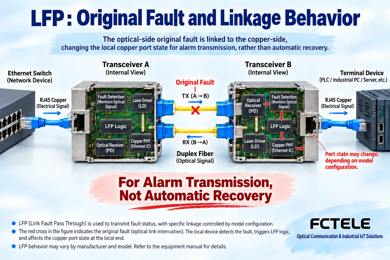
The FCTEL remotely managed single-optical/single-copper Gigabit series lists LFP, power-loss detection and local/remote management. Appropriate versions can combine management and site measurements for line/power clues. Ordinary converters do not automatically have these functions. An LFP LED may only indicate enabled status, not a current fault.
Simulate failures in isolation or an approved window with recorded settings and stop conditions. Disconnect only permitted sections and observe alarms/recovery. Do not pull production fiber merely to test LFP. Temporary service after disabling propagation cannot prove the root cause is removed. Assess upstream/service effects before changes.
6. With normal LEDs, test service rather than pulling more cables
Inspect errors/discards, then VLAN, IP, gateway, access policies and services. Background broadcasts may blink LEDs despite a wrong destination address. Ping is a reachability clue, not sustained throughput or all applications. Verify both directions with documented tools, load and observation time.
For intermittent video despite established links, save error, power and application timelines and plan segment tests instead of resetting everything. After recovery verify original service, link rebuilding and alarm clearance. Handover should include model, topology, original fault, actions, measurements and retests, not simply cable changed and fixed.
Product references:FCTEL managed converter categories and single-optical/single-copper Gigabit details; copper features refer to B-series details. LED differences refer to specified-model LFP and LED documentation, not universal FCTEL specifications. Figures are generic, not measurements or product photographs.
Translated from the Chinese technical article. Source first published: 2020-05-26. Source last revised: 2026-10-13T15:39:27+08:00. Read the Chinese source
