


Choose converters by matching endpoint Ethernet rules, then fiber and power budgets, and finally actual load and environment. Price, metal, Gigabit and long-distance labels are not independent pass criteria. Define interfaces, optical parameters, power, installation and acceptance before asking which brand is best.
1. Define the connection problem
Here a converter is Ethernet media-conversion equipment, not every dedicated optical terminal. It carries copper electrical signaling over fiber and back. Optics encode information in light and recover it. Internal Layer 2 switching/buffering may exist but does not imply routing, PoE or serial protocol conversion.
List terminals—switches, IP cameras or servers—required copper ports and present/future traffic. Establish whether the peer already has optics or needs a converter. Two copper-only ends normally need two units; a compatible optical peer may need only one. Existing optics still require matching. Ethernet cannot be connected directly to arbitrary PON or video-optical ports.
When replacing one endpoint, retain its full label, model, interface definition and service documentation. Repeated trial connections cannot identify an unknown dedicated optical protocol. Photos show mechanics, not compatibility. Identify telephone, video or serial systems before deciding on an Ethernet replacement.
2. Separate copper negotiation from optical compatibility
10/100/1000M normally describes copper rates, not arbitrary Fast Ethernet/Gigabit optical switching. Verify copper standard, negotiation and duplex separately from optical standard, rate and module support. Fixed optics require unit specifications; SFP requires both host and module specifications. Form factors cannot override speed, media or host limits.
Modern point-to-point Ethernet normally uses full duplex. Older hubs and half-duplex equipment have collision-domain and timing limits. Do not require half duplex in every new project unless legacy equipment needs it. Validate any forced/automatic settings combination. Automatic wire crossing depends on Auto-MDI/MDIX; old Uplink rules are not universal.
Different brands are not inherently incompatible, and one brand does not guarantee every model combination. Confirm exact devices, modules and firmware, then test negotiation, forwarding and recovery. IEEE 802.3 wording alone does not cover all optional functions. The old simplified claim that 46-bit delay determines distance is not a universal modern procurement measure.
3. Buffers do not guarantee zero loss
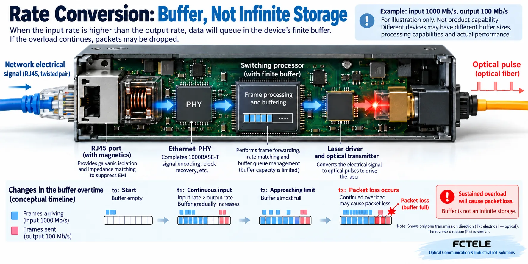
Some Layer 2 designs receive frames and queue them for forwarding. Buffers are finite waiting areas. Bursts can be absorbed, but sustained input above output capacity eventually overflows. In a hypothetical supported rate-conversion design, near-Gigabit input cannot indefinitely leave a Fast Ethernet output losslessly regardless of buffer size. This is capacity, not terminology.
Register transfer, large buffer or switching chip alone cannot prove quality. Request documented throughput, forwarding, buffer and flow-control conditions, then test actual traffic. Flow control may pause upstream senders and affect latency or other services; it is not universally safe to enable. Nominal port rate is not useful application throughput. Multiple copper inputs must share sufficient output capacity.
4. Evaluate both optical endpoints, not distance alone
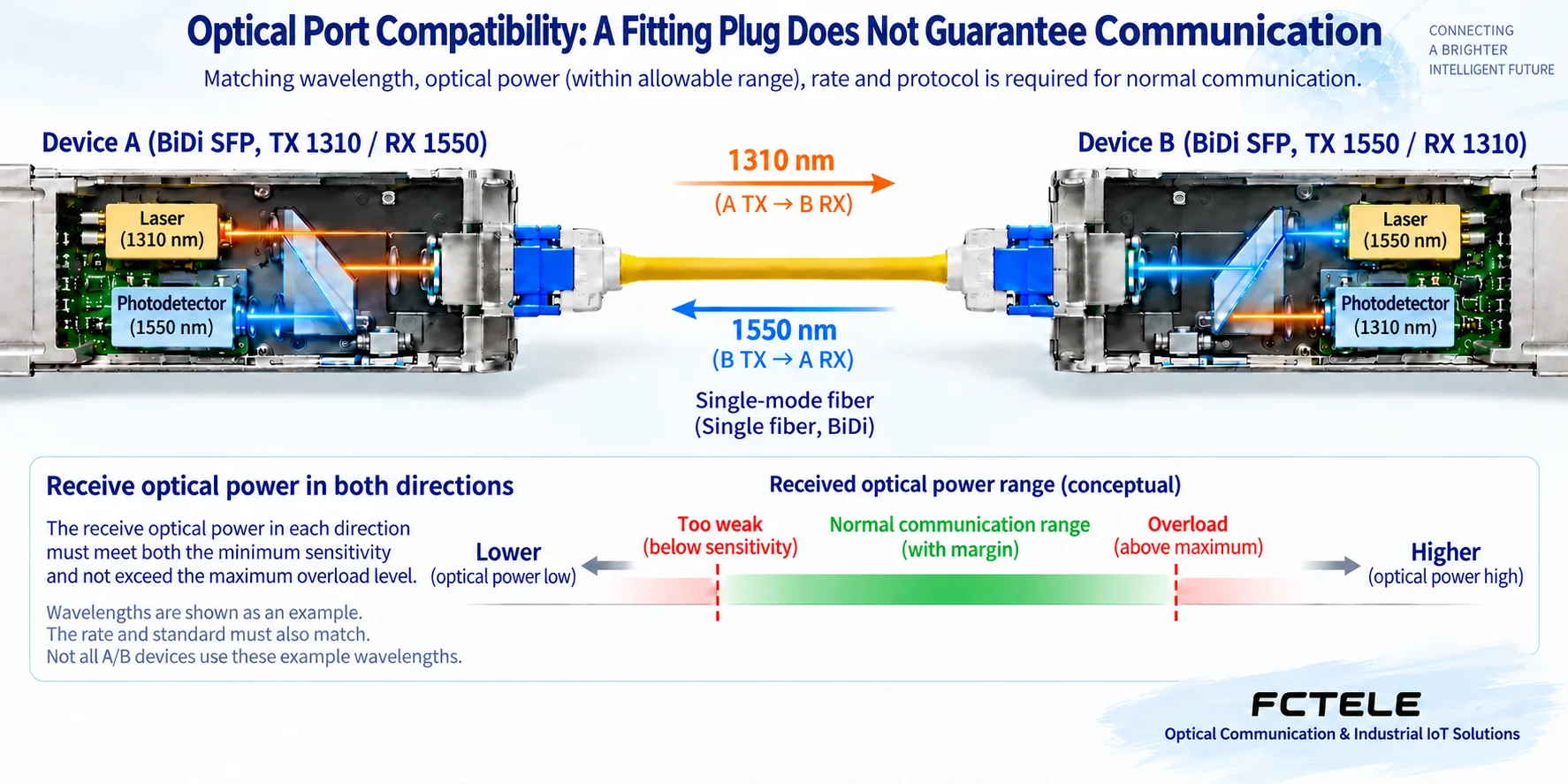
Identify installed mode, core count and connectors first. Duplex TX connects to remote RX; single-fiber BiDi needs complementary wavelengths rather than identical-role units. Connector form, UPC/APC polish and fiber type are separate checks. Mechanical mating does not establish optical compatibility.
Rated reach assumes conditions, not a site guarantee. Estimate loss budget from minimum transmit power and receiver sensitivity, then include fiber, connectors, splices, other losses and engineering margin. Budget both directions. For high-power long-reach optics on short links, check maximum transmit power against peer overload. Design attenuation from specifications rather than guesswork.
Transmit range, sensitivity, overload and fiber requirements are more useful than a 20 km label. Measure receiving power with the correct wavelength and inspect end faces/bends. Do not judge safety or compliance by looking into ports or using ordinary cameras. For classifications and wiring, see fiber converter classification, pairing and installation troubleshooting.
5. Translate industrial claims into actual environment and installation
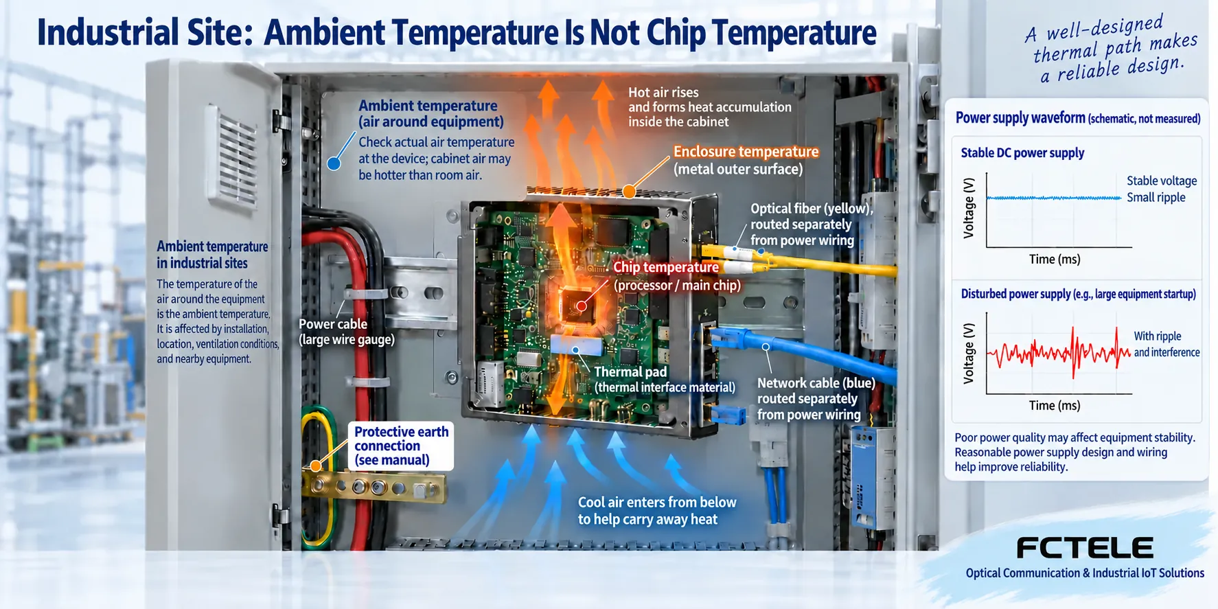
Assess cabinet temperature, humidity/condensation, dust, vibration, supply fluctuations, interference and space against complete-unit specifications. Operating, storage, case and chip temperatures differ. One chip maximum is not a system ambient limit, and 85°C is not universal.
Heat passes through conductive paths, enclosure and air. Crowding, blocked ventilation and nearby supplies can raise local temperature above expected room conditions. Pluggable modules have their own temperature, consumption and host requirements. Metal, rail mounting and an industrial name cannot replace verification.
Specify input range, polarity, consumption and supply arrangement. Follow manuals/site rules for grounding and shielding. Verify redundant power, surge protection, isolation and EMC by model and test conditions. An IP rating does not itself establish lightning or outdoor deployment suitability. Include the box, connector protection and cable route in an outdoor design.
6. Make acceptance measurable
Test known-good cables and a safe short optical link first, checking negotiation and pairing. Introduce the field route and measure both directions. Run actual services or agreed load and record throughput, loss, delay and errors. LEDs and ping cannot prove sustained heavy traffic, bidirectional operation or reconnection.
For four aggregated cameras, include ordinary traffic and bursts from scene changes, playback or concurrent access, checking converter output and upstream capacity. Agree scope, duration, tolerances and recovery requirements rather than inventing universal values. Arrange maintenance windows before power/fiber failure tests.
Change one condition at a time: a short copper cable, known-compatible module or individual fiber segment. Distinguish CRC errors, congestion drops and application timeouts. Retain models, optics, firmware, wiring, power and results. Verify LFP/FEF separately; fault propagation is not automatic repair.
For central deployment distinguish desktop, fixed optics, pluggable modules and chassis cards. Cards save space but do not automatically add redundancy or management. Pluggability aids selection/replacement but does not permit every module. Fiber carries no PoE energy. Include chassis, management units, adapters and spares so the delivery is a complete system rather than merely a card that fits.
7. Require product and support evidence
The FCTEL single-optical/four-copper Gigabit converter offers a multiport arrangement for aggregation, but verify configuration, output capacity and power options rather than extending it to every series. For industrial applications start with the industrial converter categories and request current specifications and supported modules.
Confirm warranty scope, response channels, spares, repair process and end-of-life alternatives rather than verbal promises. Archive supplier-confirmed combinations, firmware, optics and baselines for replacement comparisons. Acceptance rests on matching parameters, passed site tests and complete maintenance information, not one brand, price or adjective.
Technical reference:MC220L official specifications illustrate checking copper and optical capabilities separately; they are not FCTEL parameters. Figures are checked generic mechanisms, not products, internal designs or measurements.
Translated from the Chinese technical article. Source first published: 2019-07-18. Source last revised: 2026-10-13T16:50:29+08:00. Read the Chinese source
