


Choosing converter chips requires more than Gigabit or industrial-grade labels. Define copper-to-optical connections, verify operating modes, interface levels, power and clocks, then validate the complete unit under actual load and environment. A chip capability establishes a design possibility, not an enabled finished-product feature or compatibility with every module.
1. Draw the required device task first
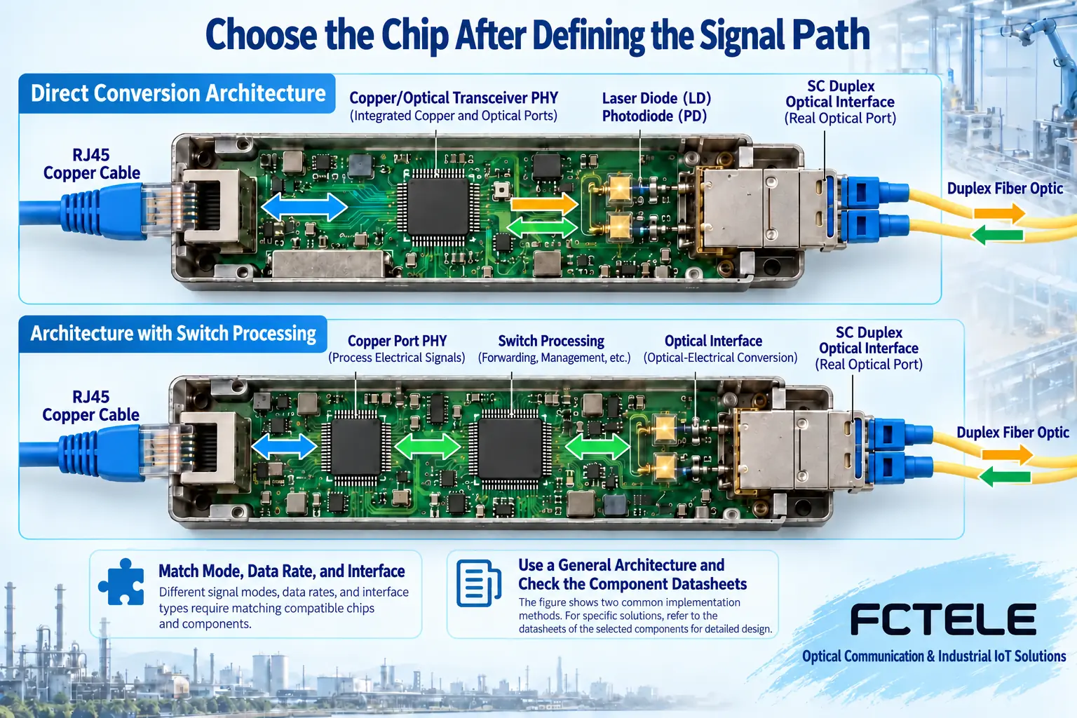
An Ethernet converter connects twisted-pair communication to fiber. Copper circuitry handles line signaling, while the optical side interfaces to appropriate transmit/receive circuits. This is more than changing a plug: rates, coding, timing and link establishment must match. Specify copper rate, optical interface, port count, buffering and management before comparing devices.
One approach uses a media-conversion PHY; another combines copper PHY, switching and optical interfaces. PHY circuitry transmits, receives and processes physical line signals. Switching may forward frames, learn addresses and buffer data. Do not merge these into a universal conversion chip or infer a single-chip interior from the enclosure or port count.
TI DP83869HM documentation describes copper/fiber interfaces and media-conversion modes as one architectural example. It does not prove use in FCTEL products or arbitrary rate conversion. Check every supported copper/optical/internal-interface combination in the actual datasheet.
2. Equal rates do not guarantee direct interface connections
A chip line interface to cabling differs from its board interface to processing circuitry. RGMII and SGMII name particular interface methods, not RJ45 connectors or optical wavelengths. Matching-looking rates still require timing, levels, pins and modes to match. An interface-capable chip cannot necessarily use every pin simultaneously in every configuration.
Check electrical input to the optical module, link-status representation and transmit/receive connections. Identical pluggable form factors may hide different rates and electrical characteristics. Fixed optics and pluggable modules have different requirements. Create a direction list matching each output to the proper input, including status signals, instead of matching names alone.
If rates differ, identify which circuit handles adaptation and buffering. A buffer is a temporary queue, not unlimited absorption of faster sustained input. Verify flow control, long frames and forwarding behavior separately. Ethernet forwarding does not imply serial, telephone or arbitrary application conversion.
3. Treat power, reset and clocks as one startup sequence
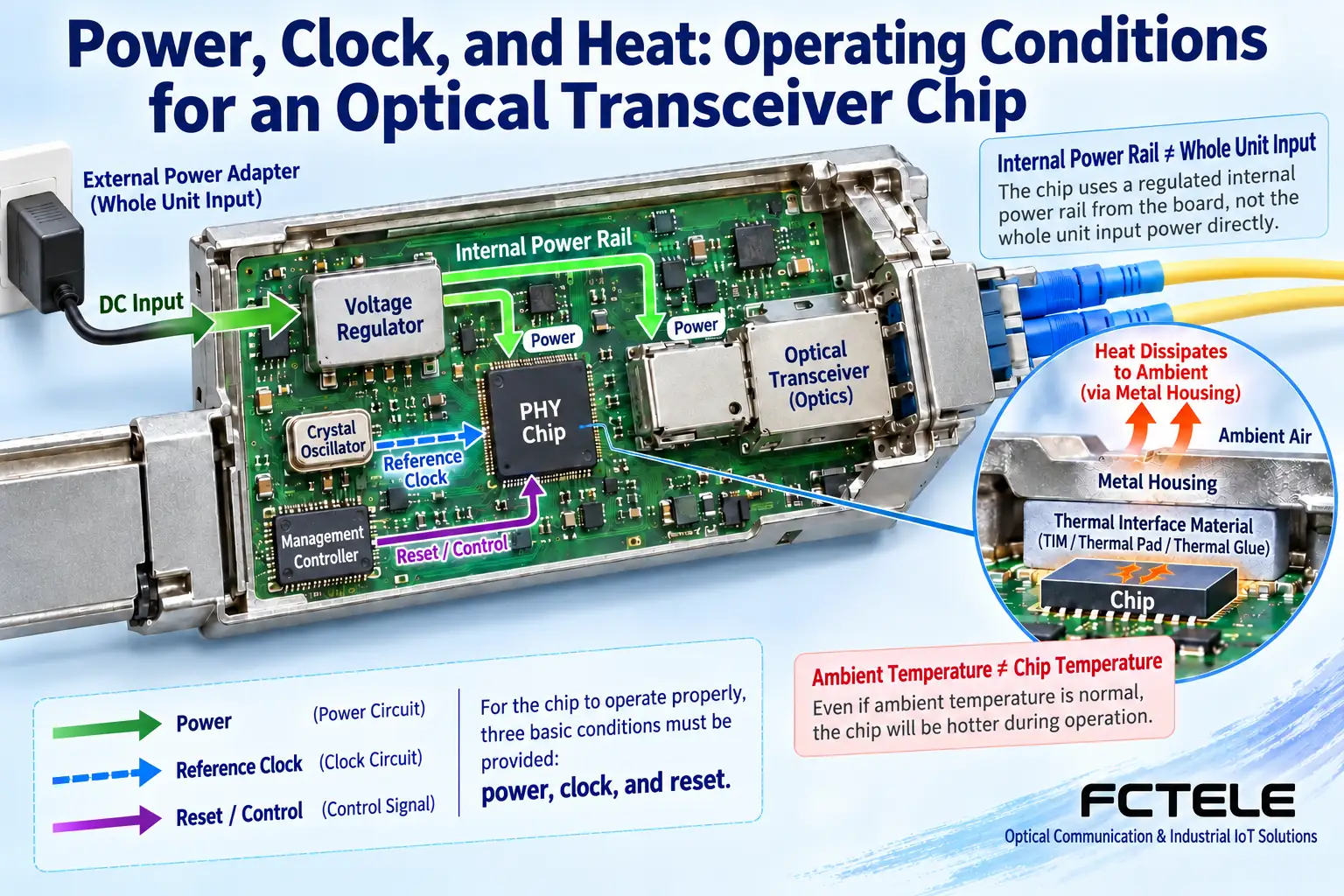
External input passes through protection and regulation to component rails. Chip cores, I/O and optics may use different voltages. One pin voltage is not the complete-unit input. Old simplified fixed-voltage rules are unsuitable for universal selection. Check recommended conditions for every component and the actual design.
Startup needs more than a PWR LED. Voltage rise, reset release, reference-clock stability and configuration loading must meet device requirements. Reset establishes a known state; clocks establish processing timing. Incorrect sequence or mode may cause no link, restarts or failure at one rate, not necessarily faulty fiber.
Configuration may use hardware straps, registers or firmware. Registers are software-readable/writable control and status locations with defined limits. Record actual mode and status after power-up rather than trusting expected settings on an interface alone.
4. Industrial suitability cannot come from one chip
Chip temperature conditions differ from permissible complete-unit ambient temperature. Self-heating raises chip temperature above cabinet air, and connectors, optics and supplies have their own limits. Relate dissipation, mounting, thermal structures and environment. Fanless does not mean no heat, and metal does not guarantee cooling in every installation.
Distinguish component ESD/surge/EMC tests from system tests. A pin passing a test cannot establish equal protection at every assembled port. Protection, layout, shielding, enclosure and grounding act together. For certification requirements, obtain reports covering the actual model/version rather than substituting an industrial label.
5. Management is a system, not an extra register
Status registers only begin collection. A finished unit also needs management processing, software objects, permissions and a reachable path. Link-status queries do not imply optical-power reading. A management interface does not automatically provide web or SNMP. Define observable and writable items and what survives link loss.
The FCTEL remotely managed Gigabit page describes switching plus FPGA and companion management. This shows how some products combine circuits and software for maintenance, not the architecture of every converter or identical fields in all order versions. Verify exact model, firmware, companion equipment and management objects.
6. Move from sample verification to complete-unit acceptance
Verify supply, modes and port state first, then bidirectional forwarding. Add load and record errors, losses and recovery. On optics, check fiber, wavelengths and directional budgets. Both weak and excessive power can cause faults. Do not reuse an unexplained power interval from an old article or inspect ports with your eyes.
Change one controlled condition at a time. Confirm basic sample function with a verified short link before the installed segment; confirm normal startup before comparing environments. Qualified personnel should perform internal measurements or modifications under manuals. Users ultimately accept the complete unit, site service and maintenance boundaries rather than a chip page maximum.
References:TI DP83869HM official documentation;FCTEL remotely managed Gigabit converter documentation. Figures show generic mechanisms, not measurements or a specific model circuit.
Translated from the Chinese technical article. Source first published: 2019-08-12. Source last revised: 2026-10-13T16:02:51+08:00. Read the Chinese source
