


On an industrial switch copper port, automatic adaptation usually means negotiating a supported speed, duplex and related mode while establishing a link. It selects a common connection mode; it neither adds bandwidth nor makes every NIC, optical module or cable compatible. Understanding negotiation helps explain a Gigabit port connecting to a PLC at only Fast Ethernet and why a lit link can still perform poorly.
Before application data, the PHY exchanges capabilities
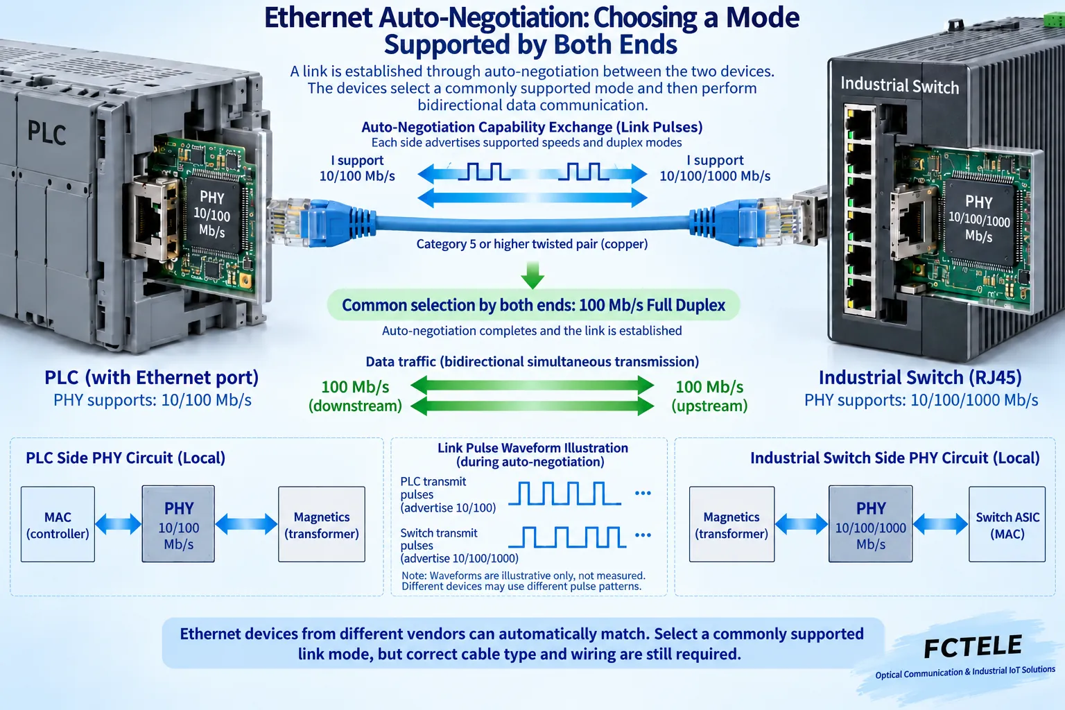
A physical-layer chip, commonly called a PHY, converts digital data into copper electrical signals and recovers it at reception. Auto-negotiation uses physical-layer capability advertisements, not an application message sent after acquiring an IP address. In common copper Ethernet, endpoints advertise supported modes during establishment, select a common capability according to the rules, and complete relevant training before carrying ordinary traffic.
Suppose a PLC supports 10 and 100 Mb/s while the switch supports 10, 100 and 1000 Mb/s. With both correctly negotiating, 100 Mb/s can be their common speed. A Gigabit switch does not upgrade the PLC port, and that PLC does not force every other switch port to Fast Ethernet. Each link establishes its own mode; internal forwarding then handles traffic between ports.
Full duplex does not double one-way speed
Full duplex permits simultaneous transmission and reception. A 100 Mb/s full-duplex link can operate at that rate in each direction; it does not carry 200 Mb/s of application data in one direction. Half duplex shares transmission opportunities and handles collisions differently, which matters for legacy compatibility. Compare actual operating states rather than only rates printed on equipment.
Negotiation can also involve flow-control capabilities. Advertising support, enabling a setting and actually sending pause requests are different events. Pause can relieve buffers under certain conditions but propagate waiting upstream. Support does not establish lossless behavior, low delay or compliance with control cycles. Assess the application’s tolerance and equipment guidance before using it.
One forced end and one automatic end can mismatch legacy duplex
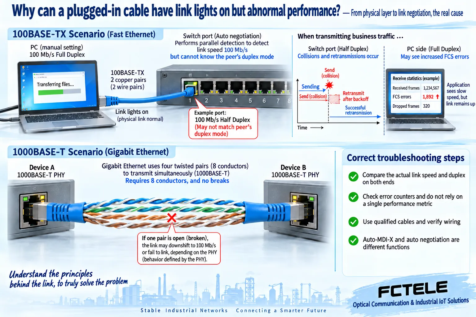
On older 10/100 Mb/s links, forcing one end to 100 Mb/s full duplex while leaving the other automatic can let parallel detection identify speed without a complete duplex advertisement. The automatic end may consequently use half duplex. Both can show link-up while following different transmit rules, exposing collisions, retries or frame errors under bidirectional load. Check the platform and PHY documentation; do not mechanically generalize this legacy example to optical or high-speed interfaces.
Where both devices support it, automatic operation at both ends is usually a useful baseline. If legacy equipment requires manual settings, verify both speeds and duplex through the change procedure. Gigabit copper also has master/slave and training requirements. Forcing Gigabit does not bypass physical-layer rules. Do not repeatedly disable production ports without backups, a maintenance window and recovery access.
Gigabit dropping to Fast Ethernet: check pairs and shared capabilities
Common Gigabit copper Ethernet uses four wire pairs, whereas ordinary Fast Ethernet twisted-pair links have different pair requirements. A partial cable fault may prevent the expected Gigabit link, causing downshift or failure depending on the PHYs and settings. Identical plugs do not certify termination, pinout or high-frequency performance. Four conductors carrying Fast Ethernet is not complete Gigabit acceptance.
Check capabilities and actual modes at both ends, then compare a known-good cable with suitable length and category. Observe link events, CRC/FCS errors, discards and application retries. Cables, ports, interference, duplex and load can produce errors; an increasing count does not establish a unique cause. An inexpensive continuity tester finds some wiring faults but cannot replace transmission-performance certification.
Automatic crossover, rate limits and optical ports are separate
Auto-MDI-X handles wire-pair connection roles on applicable copper interfaces; it is not another name for speed negotiation. Support for one feature does not establish the other in every mode. Traffic rate limiting can leave the physical link showing Gigabit. Conversely, a negotiated Fast Ethernet link lacks Gigabit wire capacity even without a configured limiter.
SFP host/module matching additionally involves type, rate, wavelength, encoding, optical budget and the peer. Copper automatic adaptation does not make optical modules arbitrarily interchangeable. FCTEL’s four-10G-optical/eight-Gigabit-copper Layer 3 product lists copper and optical speeds separately, illustrating the need to check each interface class. One model’s multirate support is not universal across products or installed modules.
Record both endpoints rather than just an illuminated LED
Record device and port IDs, both configurations, actual speed/duplex, cable specifications and starting counters. Conduct approved bidirectional application tests, then compare error increments, stability and responses. Mark changes in cabling or settings so several variables are not changed together and assigned an intuitive cause. A healthy port is only part of connectivity; IP, VLAN and application services also require checks.
For specification meanings, see Switch capacity and uplink bottlenecks; for methods, see Throughput, latency and frame-loss acceptance. References include Cisco Ethernet auto-negotiation troubleshooting and FCTEL corresponding product details. Cisco commands are not prescribed for FCTEL equipment. Figures illustrate generic mechanisms, not measured waveforms.
Translated from the Chinese technical article. Source first published: 2021-03-04. Source last revised: 2026-10-13T14:28:14+08:00. Read the Chinese source
