


Audio fiber equipment carries sound signals between locations, such as buildings, recording points, surveillance centers or stage and control positions. It replaces the long transport span, not microphone preamps, mixing consoles or power amplifiers. Defining interfaces and directions first is more useful than starting with maximum distance.
What changes between sound and fiber
A microphone converts air vibration into an electrical signal that varies over time; a mixer’s line output supplies processed audio voltage. In a common digital transport product with analog inputs, the transmitter conditions amplitude and filters unwanted high-frequency components. An analog-to-digital converter, ADC, reads voltage at successive instants and represents amplitude numerically. Sampling and quantization describe the electrical sound signal; numbers are not a different kind of sound.
The equipment arranges samples from its channels into a transport stream and drives an optical transmitter. At the other end, a photodetector converts light changes into electrical signals, receiving circuitry recovers data and timing, and channels are separated. For analog-output products, a digital-to-analog converter, DAC, and reconstruction filter restore continuous voltage for a mixer or amplifier. Encoding, channel arrangements and optics must match; fitting plugs are insufficient.
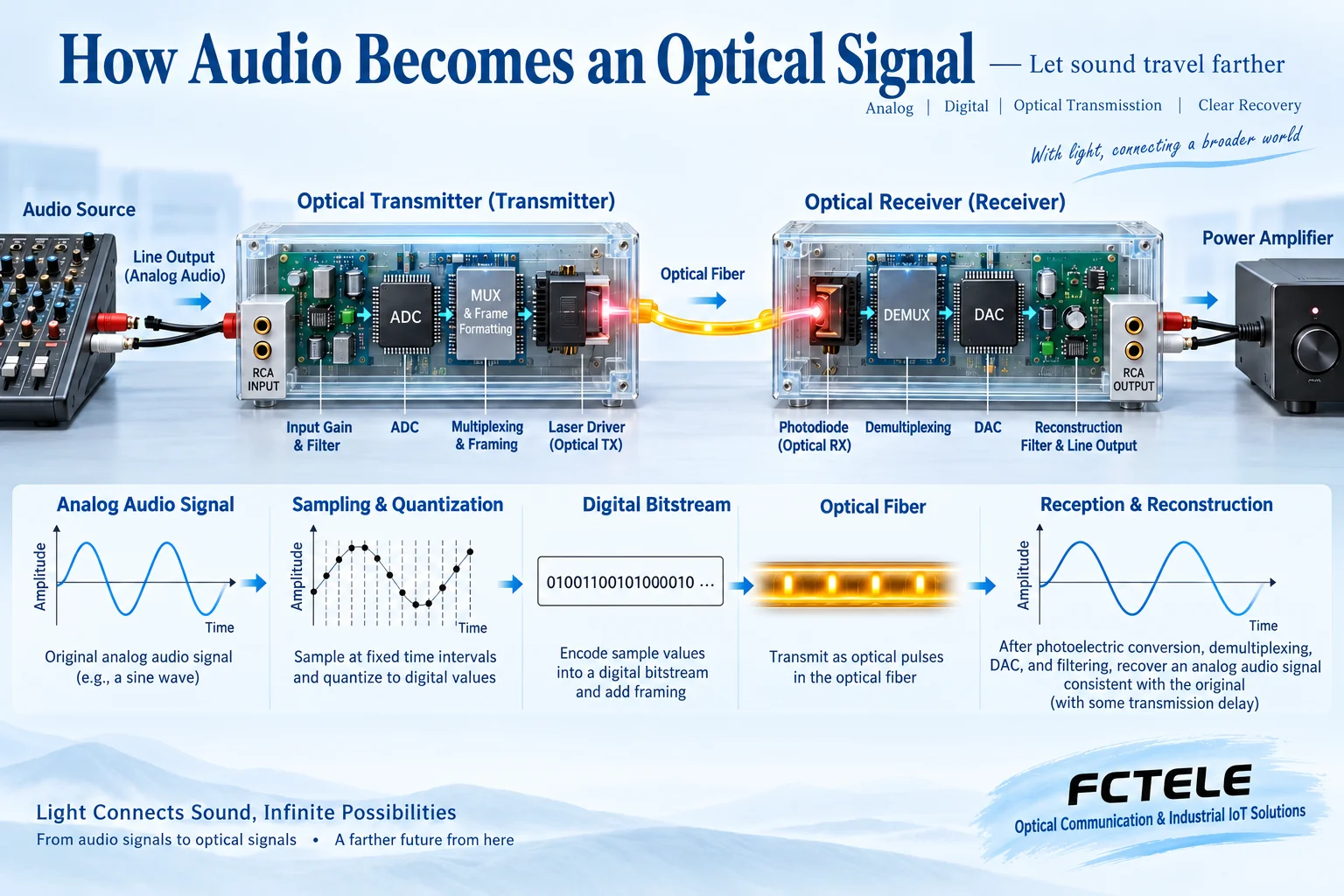
Digital-input products may receive audio already digitized and need not perform another ADC conversion. Analog XLR, digital AES/EBU and Ethernet audio all carry sound but have different electrical and protocol requirements. A common connector shape does not make ports interchangeable, and matching optical connectors does not establish compatible line coding.
Applications that benefit
Broadcast facilities to remote equipment rooms, or campus control rooms to other buildings, are straightforward examples. Mixer output feeds the transmitter; the remote receiver feeds a local amplifier that drives speakers. The optical unit normally supplies a signal, not loudspeaker power. Several zones receiving one program require an explicitly supported point-to-point, aggregation or distribution architecture. A passive optical splitter does not automatically turn an ordinary link into a broadcast system.
Remote recording, broadcast acquisition and professional audio distinguish main-program, monitoring and return channels. Remote initially means audio extension between a field site and control room or fixed locations; it does not automatically imply public-Internet conferencing. For stage levels, bidirectional paths and return delay, see Professional audio connection and acceptance.
Surveillance can carry a suitable pickup output to a monitoring center; simultaneous video requires a corresponding multiservice model. Conferences, classrooms and transport announcements can also use audio extension, but two-way speaking, echo handling, emergency priorities and audiovisual synchronization remain system-design issues. An ordinary audio port does not supply telephone line feed, ringing or off-hook signaling and cannot replace telephone FXS/FXO.
Fiber’s advantages do not remove equipment limits
The glass span avoids copper-current transmission and can reduce long-cable electromagnetic coupling and conductive connections between sites. Analog cables before and after it can still introduce noise, and power and enclosures require correct installation. Temperature, moisture, surge and protection ratings are model-specific, not implied by fiber. Cable containing metal strength members is not simply a wholly insulating cable.
Optical signals also attenuate. Length, splices, connectors and bends affect received power. Too little can interrupt service; too much can exceed the receiver’s window. Check transmitter power, sensitivity, overload and actual loss with reasonable margin. A distance label assumes specified conditions, not every field installation.
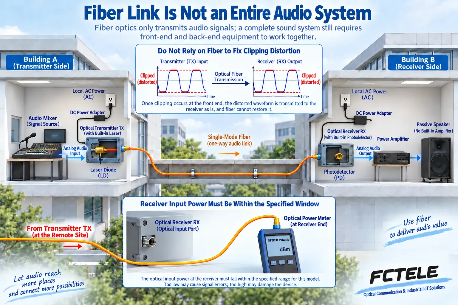
Fidelity concerns the complete chain. An overloaded input remains distorted after digitization. Sampling rate, effective dynamic range, frequency response, noise and downstream load also matter. Uncompressed digital transmission is neither absolutely lossless analog end-to-end transport nor zero latency. Fiber is not encryption. Sensitive applications need separate access control, site/route protection and end-to-end encryption assessment.
Build a checkable interface schedule
Record each source’s connector, analog/digital type, level and destination. Stereo commonly uses separate left and right channels; do not count a stereo pair as one mono channel. List both directional channel counts and whether microphone gain, phantom power or other services are needed. Then verify fiber, core arrangement, complementary wavelengths, connectors, supply and environment. Channel count follows the equipment’s multiplexing capacity, not automatic allocation by the fiber itself.
FCTEL’s digital audio product category includes RCA, XLR and AES/EBU input types. Start from the actual signal, then verify direction and the ordered model configuration. One model’s balanced interface or power feature is not universal. For coordinated systems, see Multimedia audio and audiovisual synchronization.
Acceptance needs more than an optical LED
First use a safe short link and known sources within the permitted input range, testing channels individually. Listen initially at low volume for numbering, stereo correspondence, noise and obvious distortion. Then connect the installed fiber and record supplies, optical power and sound performance. Never look into ports or remove protective grounding to investigate noise. Link-up cannot certify analog wiring or direction.
For silence, follow source output, transmitter input, fiber, receiver output and downstream mute. For distortion, inspect gain and downstream loading first. For intermittent service, record power changes, supplies and connectors. Handover should include model, mapping, routing, measurements and maintenance limits, rather than a claim that the sound is clear.
Reference note: this article explains generic digital-audio transport. Input types follow FCTEL’s category and model manuals. For sampling and front-end principles, see TI audio ADC documentation, without implying that FCTEL uses that chip. Figures are generic illustrations, not product teardowns or measurements.
Translated from the Chinese technical article. Source first published: 2024-12-27. Source last revised: 2026-10-13T14:22:45+08:00. Read the Chinese source
