


Data centers need high-speed network links matched to server, switch and storage ports; data fiber modem is not a performance standard. E1 and RS485 fiber modems serve particular low-rate applications rather than replace high-speed Ethernet. This article focuses on Ethernet optics: conversion, capacity, module selection and backup-path validation.
Separate modules, media converters and switches
An optical module normally occupies a supported host or switch slot and performs the corresponding electrical/optical transmission. It is not an independent multiport switch; power, management and data handling still depend on the host. An external media converter has its own case, supply and media interfaces for extending a copper device over fiber. Buffering, management or switching require specific product evidence.
Where switches already have suitable optical ports, compatible modules and fiber are often simpler to manage than additional boxes. A device with only 10G copper may instead justify a suitable 10G media converter. Include its power, heat, failure points and maintenance costs. More optical boxes do not inherently mean higher reliability.
How server traffic travels through fiber
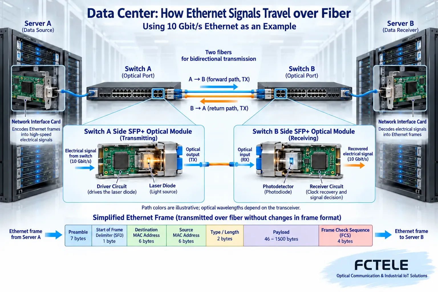
The server NIC forms Ethernet frames from upper-layer data. Interface circuitry generates electrical signaling according to the supported physical layer, and the module transmitter converts it into optical changes. The remote photodetector and subsequent circuits recover information for a switch or NIC. This remains network communication, not a file transformed into a glowing picture.
Different speeds can use different coding, modulation, lane counts and error correction. A single transceiver path explains the principle but does not establish interoperability between Fast Ethernet, 10G or faster modules. Fitting cases, common connectors and illuminated LEDs satisfy only some conditions. The supported host/module combination is still necessary.
Check bandwidth units before discussing scale
Link rates use bits per second while file sizes commonly use bytes. Eight bits make one byte: ignoring every overhead, 10 Gbit/s converts to 1.25 GB/s. Applications additionally depend on overhead, server processing, storage and shared traffic. Old claims of tens of terabytes per second need identified devices, interface counts and test conditions.
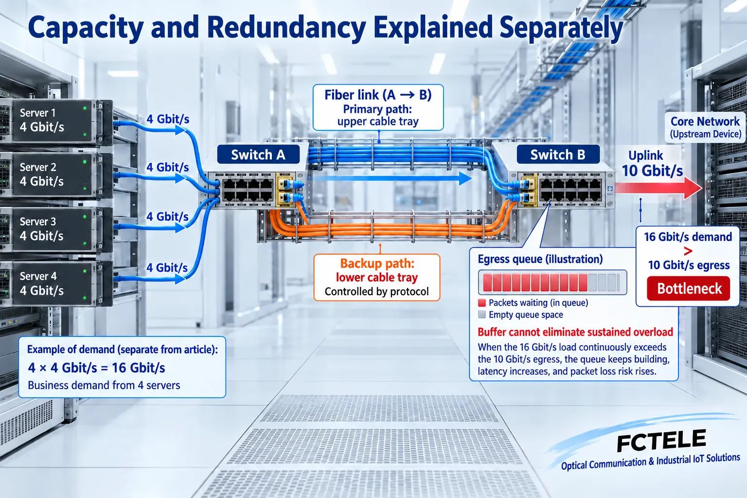
Suppose eight servers each send 2 Gbit/s to one 10 Gbit/s egress: total demand is 16 Gbit/s. Healthy access links do not prevent queues or loss at that shared egress. These assumed numbers explain oversubscription rather than prescribe a configuration. Include steady traffic, bursts and expansion margin; total room-wide port capacity is not the capacity of an individual outlet.
Check compatibility item by item
Start with supported host speeds and form factors. Then verify both optical physical standards, fiber, wavelengths, connectors, distance and receive ranges. Duplex fiber joins local TX to remote RX; BiDi requires complementary endpoints rather than arbitrary identical side configurations. Parallel multifiber optics also have lane and polarity rules; a duplex drawing cannot guide every such link.
Some high-speed links need matching forward error correction settings. FEC adds redundant coding that can recover limited errors; it cannot correct arbitrary damage or repair a severely broken cable. Host support lists and module interoperability information establish combinations more usefully than supports all protocols. Still check actual port state and errors during acceptance.
Budget optics rather than compare kilometer labels
The optical budget assesses allowed power loss between transmission and reception. Include fiber length, connectors, splices and maintenance margin. Receivers have both sensitivity and overload limits. A long-reach module on a short jumper may require attenuation according to its manual. Do not choose the strongest transmitter merely for perceived stability, or look into a port to diagnose contamination.
Record actual transmit/receive power, port errors and module temperature where supported, interpreting diagnostics under their measurement conditions. Adequate local power does not guarantee suitable received timing or application throughput. Intermittent failures also require checking supplies, host/module support, cooling and settings rather than repeatedly replacing fiber alone.
Spare fiber is not yet operational redundancy
Availability first needs fault detection, then supported forwarding changes to a usable route. Fibers on the same tray can be cut together; supplies behind one upstream breaker can share a failure. Check physical routes, equipment, power and application protocols separately rather than count spare ports.
Opening both Layer 2 paths without control can create a loop. Use properly supported and configured loop control or protection. Aggregation, spanning tree, routing and dedicated protection serve different architectures; do not combine two cores arbitrarily into one converter. The figure explains route diversity only. Switching and application recovery times require actual equipment, protocol and traffic tests.
Where a FCTEL 10G product fits
FCTEL’s FCM-10G page lists one 10G copper and one optical interface, module diagnostics, loopback testing and optical-side regeneration. It is a candidate for a copper-to-fiber extension, not an upgrade turning an E1 modem into a data-center core switch. Diagnostics help investigate optics; coordinated loopbacks can support maintenance testing.
Some standard names, cabling and power entries on that page require clarification and must not be copied verbatim into engineering guarantees. Before ordering, confirm the module version, host and peer compatibility, 10G copper category/reach, supply and cooling. Without product evidence, do not claim faster networks, every redundancy protocol or cryptographic encryption.
Accept both normal and failed states
Establish a short-link baseline using known-good supported modules and jumpers, then test the installed route. Check each direction and simultaneous load, bursts, counters, application completion and sustained operation. In an approved window, separately test fiber failure, restart and power anomalies, recording actual switching and recovery impact. Do not disconnect production arbitrarily to create faults.
Handover includes port IDs, modules, physical routes, power readings and backups. Fiber reduces some copper-span limits but does not guarantee zero latency, zero energy or permanent compatibility. Appropriate equipment and fewer unnecessary conversions are more useful than calling every optical route a high-speed data modem.
References:FCTEL FCM-10G product details;Cisco optical-interface FEC documentation. Confirm capabilities against the ordered configuration. Figures are generic illustrations.
Translated from the Chinese technical article. Source first published: 2024-06-26. Source last revised: 2026-10-13T14:22:45+08:00. Read the Chinese source
