


First draw the services at both ends, then talk about the converter
“E1 protocol converter” is a broad name. When choosing a model, first write down what service the devices at both ends output, what interfaces they need, and what kind of channel can be provided in between: is it fiber, an E1 leased line, or an IP network. Only when these three items are clear can you judge whether the device changes the transmission medium, the service bearer method, or the port electrical interface.
For example, an E1 terminal going through fiber to another E1 terminal, and a computer network going through an E1 leased line to computers at another location, although both can show an E1 port, solve different problems. You cannot assume they can replace each other just because the product names are similar or because both panels have network cable plugs.
Understanding E1: it has a fixed rate, and may also have service timeslots
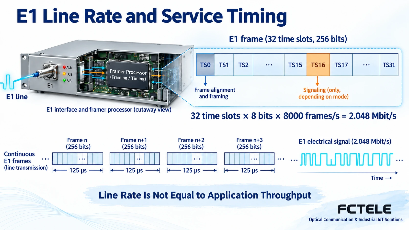
The E1 line rate is 2.048 Mbit/s. The framed structure contains thirty-two eight-bit timeslots per frame, and eight thousand frames are sent per second, so each timeslot corresponds to sixty-four kilobits per second. A timeslot can be understood as a time position that appears periodically; the same service occupies the corresponding position in repeated frames, and the receiving side extracts data at the agreed position.
TS0 is used for frame alignment and other purposes. Whether TS16 is used for signaling depends on the specific service mode. You cannot treat all thirty-two timeslots as directly usable voice channels, and you cannot write the E1 line rate as the final application throughput. Framing overhead, service mapping, and other encapsulation all affect the effective capacity; unframed transparent transmission is another processing method.
First type: E1 over fiber, terminal service unchanged
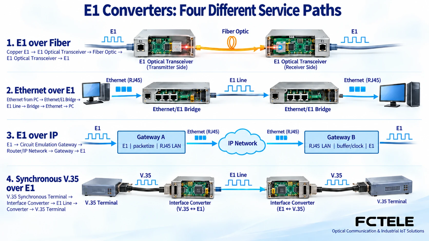
An E1 fiber modem receives the E1 electrical signal at one end, uses a matching optical line for transmission, and restores E1 at the other end. At this time, both ends are still E1 devices, and the fiber carries cross-site transmission. Internally, it must complete electrical signal reception, necessary timing recovery, and electrical-to-optical and optical-to-electrical conversion. The fiber itself does not turn E1 into Ethernet data.
Feichang Technology’s E1 fiber modem category lists framed and unframed FCP-E versions, respectively suitable for checking timeslot processing and whole bitstream transmission requirements. Model selection must confirm the optical path, interface impedance, and version pairing. Ordinary Ethernet transceivers, PON devices, or any SFP module cannot replace matching E1 optical transmission equipment just because the optical port form is the same.
Second type: Ethernet over E1, using the old leased line as a channel
An Ethernet-to-E1 bridge receives Ethernet frames from a computer or switch, maps the frames into one or more E1 channels, and restores the Ethernet frames at the far end. The service at both ends is Ethernet, and the intermediate bearer is E1. Even if the device’s electrical port can negotiate 100 Mbps, its cross-site capability is still limited by the actual number of E1 links, available timeslots, and encapsulation method.
The FCC-E16F4 details in Feichang Technology’s Ethernet-to-E1 category list one to sixteen E1 links carrying Ethernet, and involve capabilities such as GFP encapsulation and LCAS. Multi-link combination uses several low-speed channels together for a service; it does not raise a single E1 to 100 Mbps. Encapsulation, channel groups, and delay adaptation at both ends must match; network management and fault handling capabilities should be confirmed according to the actual ordered version.
Third type: E1 over IP, rebuilding a continuous circuit
An E1 over IP gateway slices continuous E1 data and encapsulates it into network packets. After passing through an Ethernet or IP network, it restores the E1 output at the opposite end. It faces traditional circuit terminals, and the network side is the bearer channel. To continuously output data from packets that arrive unevenly, the receiving side needs appropriate buffering and clock recovery mechanisms.
The details of Feichang Technology’s four-E1 circuit emulation gateway FCT-E4-M clearly distinguish the E1 service ports from the IP-side electrical and optical ports, and list Console, WEB, and remote mapping configuration. For this type of product, you must check conditions such as bearer mode, packet loss and packet delay variation, and output timing. You cannot understand E1 over IP as an Ethernet-to-E1 bridge, and you cannot assume that an ordinary network can unconditionally replace the original circuit.
Fourth type: conversion between synchronous serial interfaces and E1
Some old terminals use synchronous data interfaces such as V.35, and data transmission depends on matching transmit and receive clocks. The corresponding interface converter adapts this data to selected E1 channels; it does not read any industrial protocol and automatically translate it into IP. Pins, electrical characteristics, clock roles, and control signals are all connection conditions.
Feichang Technology groups products such as E1 to V.35 or V.24, and E1 to RS530 into corresponding series, reflecting the difference in interface objects. Before determining the model, check whether the terminal is data terminal equipment or data circuit-terminating equipment, as well as framing, rate, and cable definitions. You cannot understand a general E1 converter as a device that automatically supports E1, T1, and Ethernet; interoperability capability must be based on the corresponding model and mode.
Check by four layers to reduce buying the right name but failing to connect
The first layer is physical conditions: whether the port actually belongs to E1, Ethernet, an optical port, or a synchronous serial port, and whether impedance, power, and cables are consistent. The second layer is service mapping: the whole E1, some timeslots, or Ethernet frames, and how channel numbers, framing, and signaling correspond. Being able to connect physically only means some mechanical conditions are met.
The third layer is timing and capacity: who provides the clock, where it is recovered, and whether the bearer has packet loss, differential delay, or service contention. The fourth layer is maintainability: what alarms, loopbacks, bit error tests, and management access are needed, and which functions are provided only in a specified model or option. Network management addresses and service addresses should also be distinguished; being able to enter a WEB page does not mean the service mapping is already correct.
During acceptance, first get one service running, then verify all channels, bidirectional communication, and actual load. Save the before and after configurations, test conditions, and alarm counts, so that when problems occur there is a basis to distinguish electrical connection, service mapping, or network bearer. Temperature range, encryption, certification, and fault recovery time without supporting materials should not be treated as default capabilities of a certain type of converter.
A hypothetical scenario: how to determine the product direction
Suppose a site still retains E1 terminals, and the available resource is an optical cable between two stations; you should first evaluate a pair of E1 fiber modems. If the resource is a reachable IP network, evaluate circuit emulation and network quality. If the requirement changes to two LANs using an existing E1 leased line, evaluate an Ethernet-to-E1 bridge. This is an example of solution judgment and does not represent a customer project that has already been implemented.
Writing clearly “original service, bearer channel, remote service” is more helpful than listing compatible protocols. After clarifying the direction, then check the specific model and version, so you can explain why it is connected this way, why bandwidth is limited, and which tests can truly prove that the service meets requirements.
Documentation note: The principle diagrams have been checked against technical content and are used to explain general mechanisms. They are not product photos or measured records. Specific interfaces, modes, and capabilities are subject to the selected model, version, and on-site verification.
Verification materials:ITU-T G.703: Physical and electrical characteristics of digital interfaces
ITU-T G.704: Synchronous frame structures
Feichang Technology E1 fiber modem category
Feichang Technology unframed E1 fiber modem FCP-E
Feichang Technology Ethernet-to-E1 category
Feichang Technology 16E1-4FE bridge FCC-E16F4
Feichang Technology TDM Over IP category
Feichang Technology four-E1 circuit emulation gateway FCT-E4-M
Feichang Technology E1 to V.35/V.24 category
Translated from the Chinese technical article. Source first published: 2024-10-28. Source last revised: 2026-10-13T14:18:10+08:00. Read the Chinese source
