


First distinguish video interfaces, then discuss multiple services
When a cabinet needs to send several channels of HD video, telephone, and control data to a remote end, the difficulty is not concentrating the connectors in one box, but ensuring each signal can be correctly received, maintaining correspondence under shared transmission conditions, and being restored as needed at the far end. A multi-service optical transceiver is only suitable for this transmission segment if it explicitly supports the corresponding interfaces and combinations.
SDI is a serial digital video interface; common connections use coaxial cable of a specified impedance and BNC connectors. HDMI uses a different set of video and control mechanisms. IP cameras send network packets. All three services may carry HD video, but they are not the same signal that can be freely plugged into each other. The BNC shape also cannot distinguish analog composite video from SDI; you must check the source device menu and device documentation.
Here we use the general processing of multiple SDI channels as the main line to explain how capacity and clocking affect transmission. Outputting the same format at both ends is transmission; changing resolution, frame rate, interface, or compression method is additional processing and requires dedicated product functions. Ordinary telephone, serial port, and Ethernet combination models cannot be regarded as HD video equipment just because the name contains multi-service.
One video channel’s rate does not equal the entire device’s capacity
HD video is represented by continuous digital data. Pixel count is only one condition; frame rate, color representation, sampling method, and carrying standard also affect the rate. The common serial rate for HD-SDI is 1.485 Gb/s, with corresponding fractional rates; 3G-SDI is commonly 2.97 Gb/s. The specific format should be confirmed; all HD video signals cannot be calculated at the same rate.
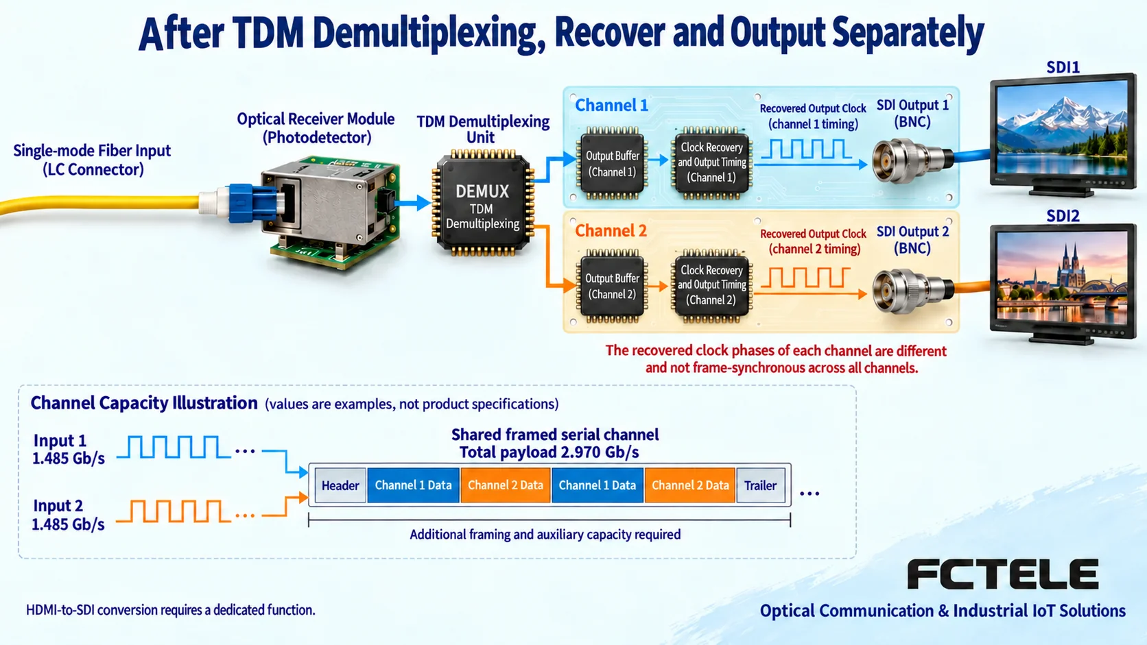
Assume two inputs are each 1.485 Gb/s; the video input rates alone add up to 2.970 Gb/s. This number does not include telephone, network services transmitted separately, or internal device encapsulation overhead, nor does it directly specify which optical port should be purchased. Actual devices may use different channel organization or optical architectures; ultimately you must look at the manufacturer’s explicitly stated simultaneous operation combinations and effective capacity.
The number of physical fiber cores, the nominal rate of the optical port, the service-side interface rate, and the available transmission capacity should be asked about separately. How many channels one fiber can carry cannot be deduced only from the words ‘one fiber.’ If the documentation only states the maximum number of video channels but does not explain the limits when network services are enabled simultaneously, an explanation should be obtained before ordering, and the agreement should be written into the acceptance conditions.
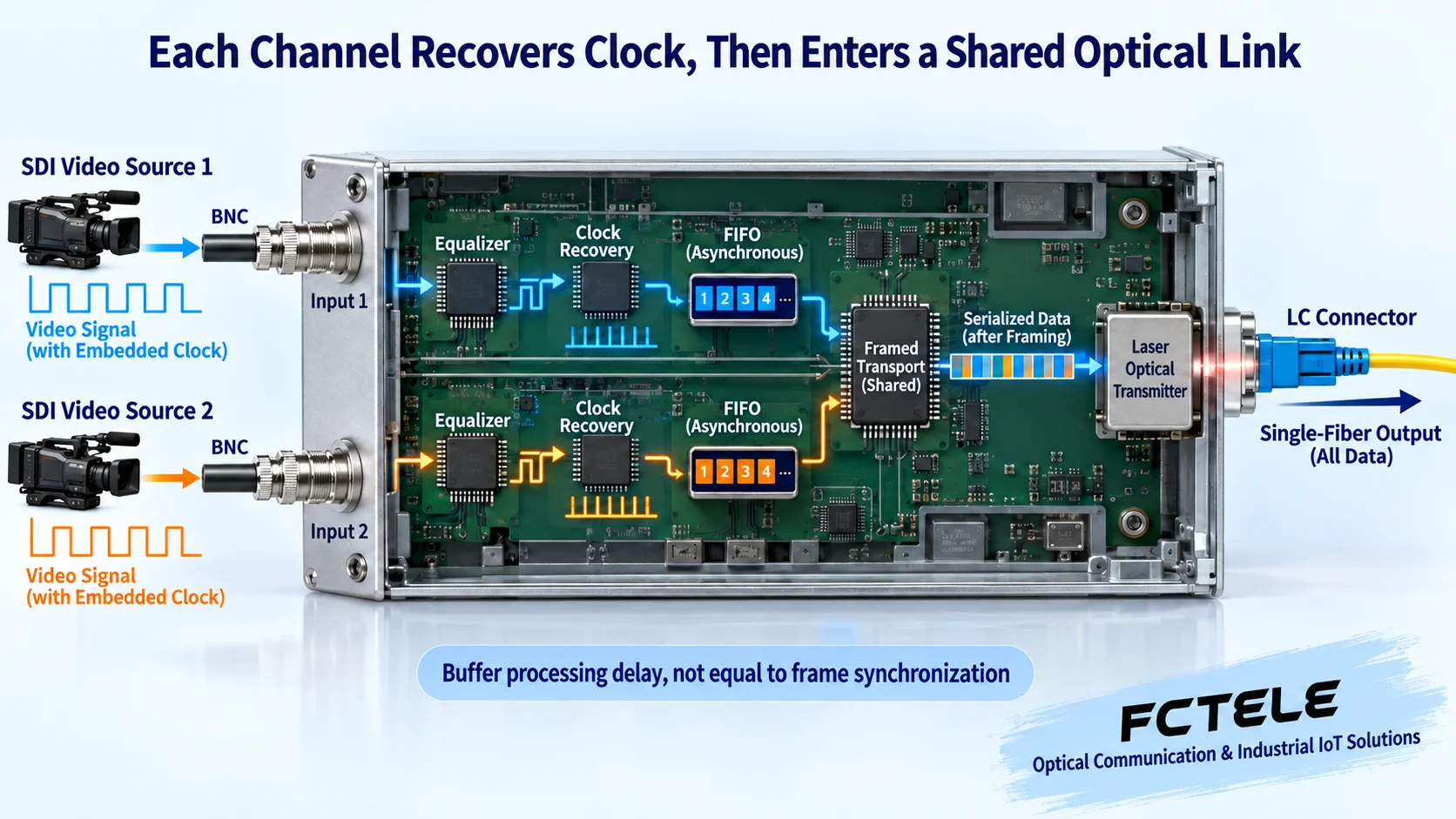
Input reception first solves waveform and read timing
Coaxial cable changes the waveform of high-speed electrical signals, and connectors and noise can also affect signal decisions. Equalization circuits compensate for cable loss within the allowed range, making pulses easier to read. They cannot extend cable indefinitely, nor can they automatically repair already severely damaged data. Whether a cable length is usable should be judged according to rate, cable material, connector, and receiver conditions.
The receiver also needs to know when to read each bit. Clock recovery obtains the read rhythm from input transitions, and retiming outputs data again according to this rhythm. Clock jitter is variation in edge timing, not objects shaking in the picture. The applicable rate and lock range must match the input conditions; the fact that a single chip can recover a certain rate does not prove that an entire Feichang Technology product supports all formats.
Several cameras may each use their own clock; even if the menus all show the same frame rate, slight frequency deviations and phases may differ. Each channel needs to first obtain its own data and timing; you cannot simply use one common clock to forcibly read all inputs. The schematic omits the specific circuit implementation; what it shows is the problem each of these stages must solve.
Asynchronous buffering and picture frame synchronization are different processes
Buffering can be understood as temporarily storing already received data so that writing and subsequent reading proceed at their own rhythms. The two sides of an asynchronous buffer can be in different clock domains; the device organizes each channel’s data in a shared channel through a specified adaptation method, and the receiving end restores each channel. Buffer depth, read/write control, and continuous rate differences must be fully designed; simply adding memory cannot guarantee it will never overflow.
Different designs may arrange time slots, encapsulate data, or use multiple optical channels; one cannot assert from the name ‘multi-channel’ that one of these is necessarily used internally. FIFO is a first-in-first-out buffer organization, not a device that high-speed video absolutely cannot use; conversely, the mere presence of a FIFO does not prove that the entire device achieves error-free operation or unlimited capacity.
Picture frame synchronization requires the frame boundaries of multiple video channels to correspond to a common production or switching time reference, which may involve frame-level storage and control, and is different from bit-by-bit clock recovery. Transparent transmission can preserve the timing of each source without turning different cameras into synchronized sources. When seamless switching on a production switcher is required, the synchronization equipment and test conditions should be confirmed separately; passing light through an optical transceiver cannot be taken as completion of frame synchronization.
What the far end restores is the corresponding service, not automatic conversion
In a shared transmission scheme, the transmitting end organizes each channel’s information, which enters the optical path through the optical transmitter section; the far-end optical receiver section restores the electrical data and extracts the corresponding channel according to rules agreed by both sides. Each output must meet its own interface and timing requirements. The fact that optical modules can be connected does not mean the service formats at both ends are compatible; confirmed matching equipment and versions must be used.
The video stream may contain synchronization markers and auxiliary data. Transparently carrying the complete signal versus extracting the active picture and rebuilding the output are different processing strategies; one cannot assume that all devices remove this information and then regenerate it. If a product claims to support embedded audio or other auxiliary content, it should be verified that the corresponding content can still be recognized at the far end, rather than only observing a static picture.
SDI entering the optical path will not naturally become HDMI. Audio de-embedding, interface conversion, scaling, and compression all require explicit functions; telephone, contact I/O, and serial port each have their own port definitions and directions. The fact that video can be displayed does not prove that reverse control works, and a lit network LED cannot replace a telephone call-in/call-out or instrument request-response test.
Use Feichang Technology’s corresponding combinations to check actual requirements
In Feichang Technology’s dedicated multi-service category, product detail 2040 lists the SDI video and telephone, network, contact I/O, or serial port combinations of FCP-V4G2O8K8, as well as the independent bandwidth description of the network channel. For sites with both video and control, this kind of explicit interface combination helps verify centralized transmission requirements.
The manufacturer should be asked to confirm the actual delivered number of video channels, allowed formats, telephone role, serial port or contact I/O options, network capacity, and versions at both ends. Similar webpage names or model numbers do not mean the interface versions are the same, and optional network management and power supplies cannot be treated as fully installed by default. The internal clock structure not described in the documentation is not presumed for this model in this article.
On site, the fiber type, transmit/receive pairing, connectors, and received power range must also be checked. Nominal distance is not an actual link measurement; splices, connectors, and bends increase loss. The equipment at both ends and the terminals still require local power; fiber does not provide copper-port PoE power. Cabinet temperature, grounding, and electrical interface protection should correspond to the delivered configuration.
Concurrent acceptance covers format changes and auxiliary services
First record each source’s interface, resolution, frame rate, and corresponding output, use a short connection to confirm that the source and receiving end are inherently compatible, then add a pair of optical transceivers and a short fiber to test channel by channel. Picture, embedded audio, control return, and other services should all be checked separately as agreed. A successful analog video test cannot be used to prove that an SDI link is qualified.
Then run all planned video and auxiliary services simultaneously. Use the agreed formats to cover dynamic pictures, audio, and necessary network load, and observe brief screen blackouts, loss of lock, audio interruptions, and control timeouts. Within the allowed maintenance window, test source-end restart or format switching and record the recovery situation; if the product does not support a certain hot switch, do not list it as an assumed capability.
For abnormalities, first distinguish whether it is one channel or all channels, then check source format, electrical connections, common power, and optical path. Change only one condition at a time, and save the normal baseline, device versions, test load, received optical power, and abnormality records. For important links, bit error or signal quality tests can be agreed upon; visual confirmation of a picture cannot be the sole basis for all acceptance.
Delivery should leave a traceable channel record
Delivery documents should include the models at both ends, ordered configuration, interface correspondence table, service directions, simultaneous operation range, optical path measurements, and recovery steps. When new cameras are added later or the video format is increased, recheck capacity and compatibility; do not assume resources are sufficient just because an empty slot is found. When backup power, optical path protection, or production-grade synchronization is required, list the functions and verification methods separately.
The value of a multi-channel HD video optical transceiver is to stably extend multiple services within explicitly supported combinations. Understanding each channel’s reception, timing adaptation, optical transmission, and output restoration is what turns the names high-speed, HD, and multi-service into checkable conditions, avoiding treating any device as a universal converter.
Documentation note: The principle diagrams have been checked against technical content and are used to explain general mechanisms; they are not product photos or measured records. Specific interfaces, modes, and capabilities are subject to the selected model, version, and on-site verification.
Verification materials:Feichang Technology dedicated multi-service optical transceiver category
8-channel SDI multi-service product details
TI LMH0346 clock recovery and retiming documentation
AMD video output asynchronous FIFO buffering conditions
SDI equalization, clock recovery, and quality boundaries
Multiplexing boundaries of telephone, serial port, and network
Translated from the Chinese technical article. Source first published: 2021-07-15. Source last revised: 2026-10-13T14:07:46+08:00. Read the Chinese source
