


First, distinguish optical amplification from optical-electrical reception
An optical amplifier increases the power of input signal light, with energy coming from an external power supply and the corresponding gain mechanism. It usually does not first read each data bit and then regenerate a data stream. Erbium-doped fiber amplifier, abbreviated EDFA, is an optical amplification device that uses erbium-doped fiber as the gain medium. This article uses it to explain the basic process and does not call all optical amplifiers EDFAs.
The receive amplifier circuit in a fiber optic transceiver usually processes electrical signals after photoelectric detection. Both have “amplifier” in their names, but they operate in different signal domains. The amplifier unit of a fiber optic sensor used for object detection also belongs to another product category. Before purchasing, clearly state whether the task is to increase communication optical power, receive network data, or read a sensor, to avoid selecting the wrong product by name.
Pump light provides energy, while service light carries information
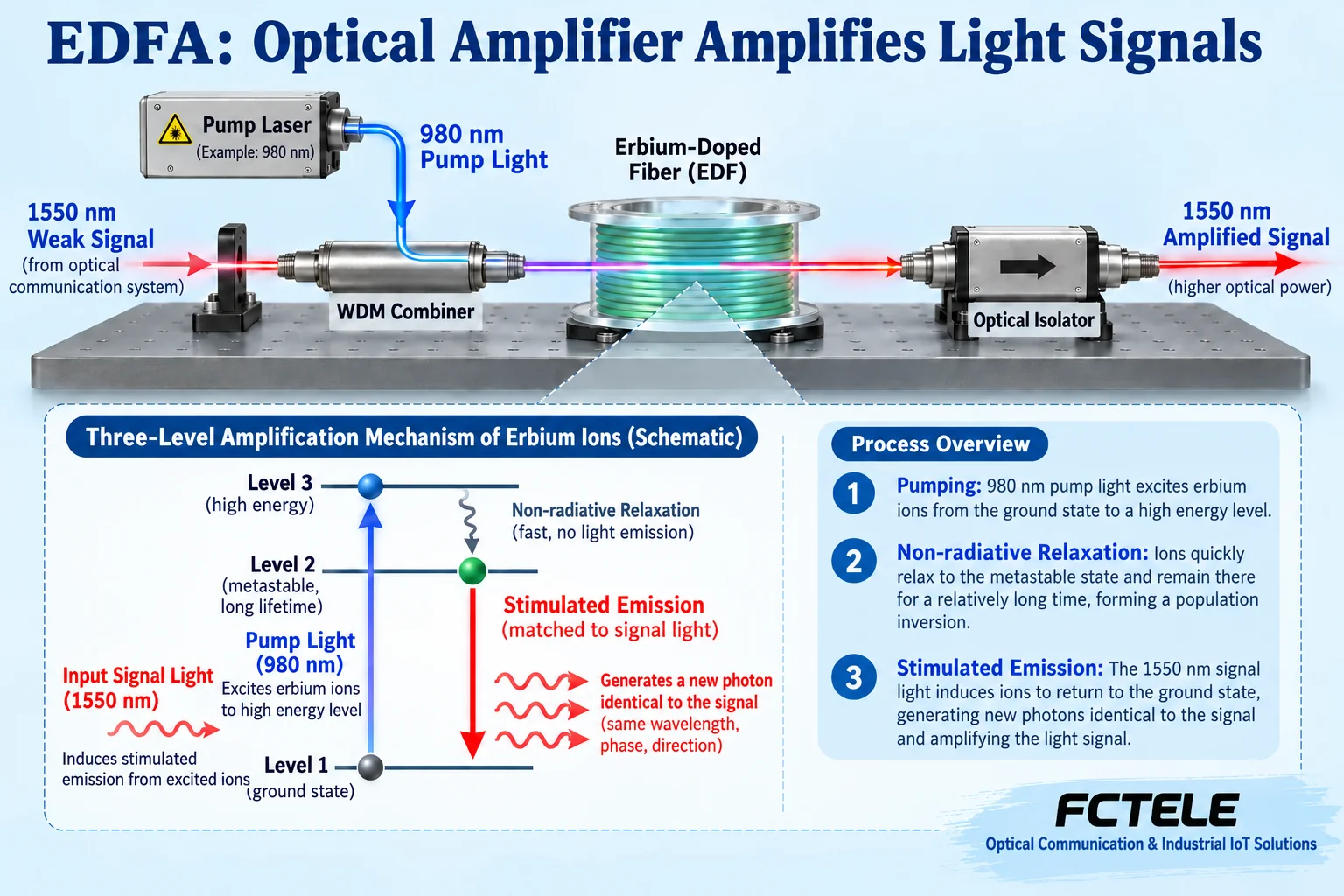
A typical EDFA structure includes a pump light source, a combiner, erbium-doped fiber, and appropriate optical components. The combiner sends pump light and signal light into the gain fiber; the pump is absorbed by the medium and provides energy. The pump is not a second Ethernet service port, nor does it mix data from another camera into the original link.
Based on common structures, we can use service light near 1550 nm and a 980 nm or 1480 nm pump for illustration; these are mechanism examples, not ordering parameters for any specific model. Pump direction, fiber length, and component layout vary with design. Whether a certain wavelength is covered must be determined by the actual gain bandwidth and module specifications, not merely by the appearance of the optical interface.
How stimulated emission gives gain to the signal
Erbium ions absorb pump energy and enter a higher energy state, then through related processes form an excited state that can participate in amplification. Under suitable conditions, the signal light induces stimulated emission, and the medium releases energy and increases the optical field matching the signal. Energy is transferred from the pump to the signal; the glass fiber does not create energy out of nothing.
The optical modulation of the input service continues to exist along with the amplified optical field, but the device does not thereby understand message addresses or video content. Wavelength, input conditions, and power range affect gain. “Amplification” cannot be understood as automatically increasing the network port rate, nor can it be assumed that a low-power input can be infinitely restored after passing through an arbitrarily long line.
Gain increases, but noise must also be evaluated
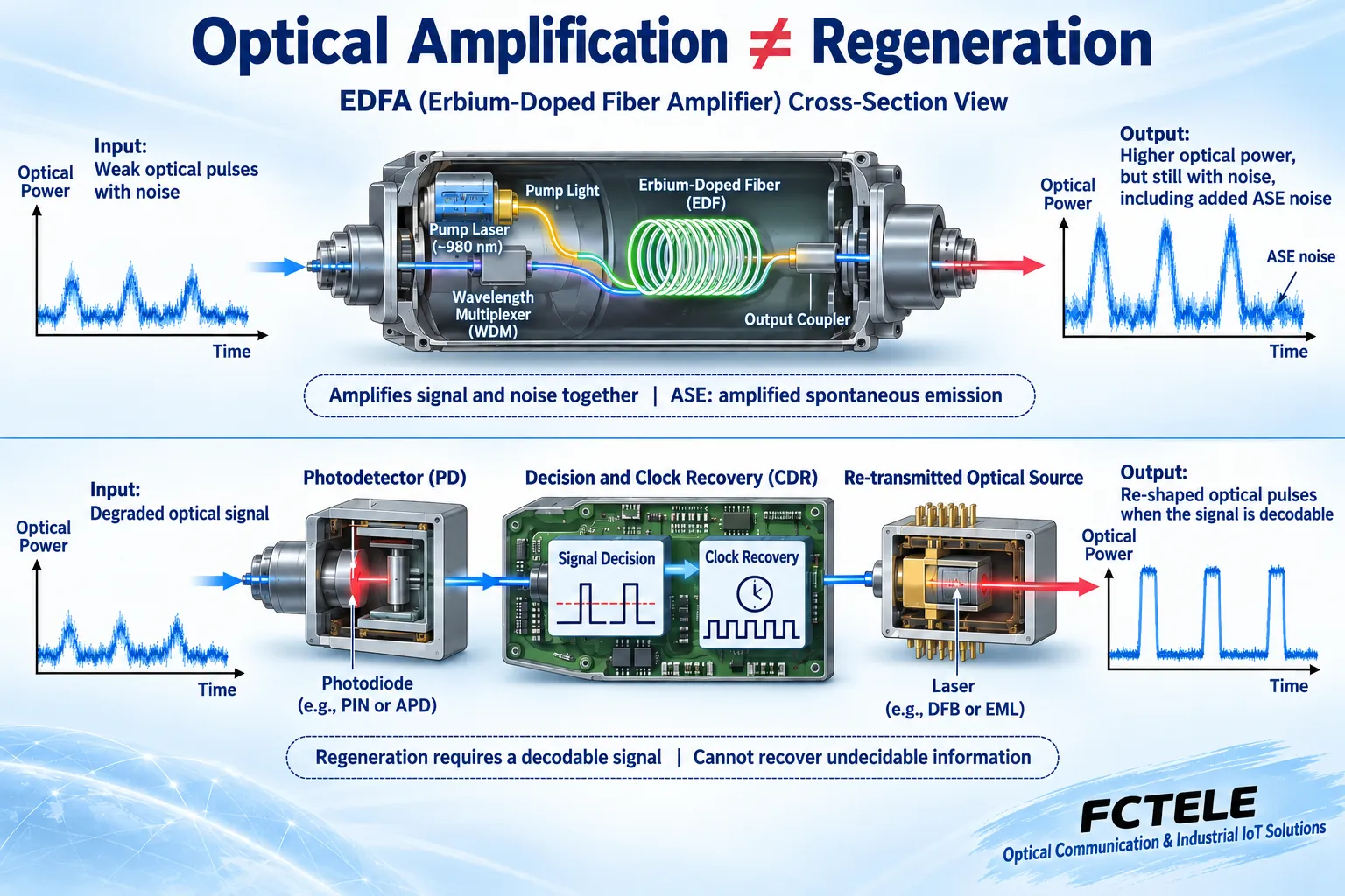
Gain describes the relationship between output and input optical power. A real optical amplifier also generates amplified spontaneous emission, abbreviated ASE, which is optical noise that must be considered. Whether the receiver can correctly distinguish information depends on the relative conditions of signal and noise, not just on an increase in the output power meter reading.
When output power is limited by power supply and medium conditions, gain saturation occurs, and it cannot increase indefinitely by a fixed multiple. Multi-wavelength systems also need to consider gain distribution among channels. During design, evaluate based on wavelength range, input and output conditions, and noise specifications; do not use “the higher the power, the more stable” as a general conclusion.
Why an amplifier cannot replace signal regeneration
Optical amplification mainly increases optical field strength; it is not responsible for realigning all pulses, nor does it eliminate existing dispersion and source-end problems. Optical-electrical regeneration first converts light into an electrical signal, decides the information under supported formats and reception conditions, and then forms a new optical signal at the transmitter. Decision and clock recovery are signal processing tasks.
Information that is already too low to be reliably decided cannot be guaranteed to be recovered through regeneration. Different regeneration devices also have ranges of supported encoding, rates, and interfaces, and cannot be described as universal repair devices. Whether to choose pure optical amplification or optical-electrical processing should be determined by line and service conditions; their latency, compatibility, and fault behavior need to be verified separately.
EDFA is not an add-on booster for all industrial optical ports
Industrial Ethernet links may use different wavelengths, single-fiber bidirectional, or dual-fiber configurations. An EDFA designed for a specific gain bandwidth cannot necessarily be used for all these paths; bidirectional links also need to consider components and architecture in both directions. The same port connector only indicates similar mechanical form; it does not prove compatibility of usable wavelengths and protocol conditions.
Actual lines may also have errors due to receiver overload, so before adding gain, both the minimum receive condition and the maximum allowed power must be checked. First inspect end faces, connectors, bends, and the original module configuration, then evaluate whether a suitable system solution exists. An amplifier cannot be used to mask incorrect wiring, nor should installers randomly try connections on an in-service optical path without a clear design.
How to read Feichang Technology product information without confusing functions
The Feichang Technology B series category provides Ethernet fiber optic transceivers; the 1-fiber 4-Ethernet details describe multiple electrical interfaces, an optical uplink, and MAC learning. These are media conversion and switching-related capabilities. They help verify industrial network access, but cannot serve as evidence that the product has EDFA gain or arbitrary-wavelength amplification capability. This article does not claim on this basis that Feichang Technology sells optical amplifiers with the illustrated structure.
If the requirement is to extend Ethernet, check the device’s optical port, peer end, rate, and loss budget; if the requirement is pure optical amplification, separately request the specifications and complete solution for the corresponding amplifier module from the supplier. When individual rate text on the official website details is inconsistent, confirm with the ordering version and clear specifications, and do not combine contradictory text into a new promise.
Form a verifiable solution from the problem symptoms
Suppose a link has insufficient received power. First use suitable tools to confirm transmit and receive conditions, then compare actual line loss with the budget. Record wavelength, fiber core, number of connectors, and test method. If power is adequate but there are errors, still check signal quality, module compatibility, and service configuration; do not just add power.
The amplification solution should have clear input range, output range, wavelength, and direction, and be accepted under the corresponding service. Keep configuration and rollback methods, and check power and error changes after inserting the device. Do not look directly into optical fiber ports; measuring tools should cover the corresponding conditions. Understanding where energy comes from and where information is decided is more useful for avoiding misapplication than memorizing a maximum distance.
Data note: The principle diagrams have been checked for technical content and are used to explain general mechanisms; they are not actual product photos or measured records. Specific interfaces, modes, and capabilities are subject to the selected model, version, and on-site verification.
Verification references: RP Photonics: Erbium-doped fiber amplifiers
RP Photonics: Fiber amplification mechanisms and limitations
FOA: Fiber structure, loss, and dispersion
Feichang Technology B series fiber optic transceivers
Feichang Technology 1-fiber 4-Ethernet transceiver details
Translated from the Chinese technical article. Source first published: 2020-09-09. Source last revised: 2026-10-13T13:49:23+08:00. Read the Chinese source
