


First, separate “how many can be plugged in” from “how many can be powered”
A PoE switch supplies power to compatible terminals through copper network cables while also forwarding network data. Eight ports are just connection locations, not eight unlimited power supplies. Whether a device can join the system depends not only on its power standard and per-port requirement, but also on the total budget shared by all ports. A camera lighting up during the day does not mean there is still enough power at night for fill light, heating, or simultaneous startup.
The power sourcing equipment is called PSE, such as the PoE port on a switch; the powered device is called PD, such as a PoE-capable camera. Current loses energy as it travels along the copper cable to the far end, and inside the PD the received voltage is converted to the voltage needed by its own circuits. Therefore, the numbers on the power supply nameplate, the switch port output, and the camera’s internal load cannot be mixed into the same account.
Why a port rated 30 watts cannot directly power a 30-watt terminal
In the common IEEE 802.3af Type 1 system, the maximum power at the sourcing end is 15.4 watts, and the guaranteed available power at the powered end is about 12.95 watts; 802.3at Type 2, often called PoE+, corresponds to 30 watts at the sourcing end and 25.5 watts at the powered end. The difference between the two end numbers includes line loss under specified conditions, and it is not that the product secretly provides less power. Higher power types have their own classifications, and this set of numbers cannot be applied uniformly to all of them.
If the terminal documentation clearly requires 30 watts at the PD input, you cannot assume compatibility based only on the switch’s “30 watts per port.” You should also confirm the type, class, and actual port support required by the terminal. Mixing the terminal’s average reading with its maximum demand is also inappropriate: a camera may normally use only eight watts, but may need greater allocation capability when heating or moving its pan-tilt head.
How to make a reviewable budget for four cameras
Assume four compatible terminals each have a maximum PD input requirement of 18 watts, and according to their documentation, the switch needs to reserve 30 watts per port. This is a teaching assumption; not all 18-watt terminals are always allocated at 30 watts. The four ports together require 120 watts reserved; if a switch’s actual allocatable PoE budget is only 100 watts, even if each of the four ports supports PoE+, it still cannot promise that all four will operate that way simultaneously.
The budget should record item by item the terminal model, required standard, maximum operating state, and the allocation basis used by the switch. Devices may reserve power based on classification, negotiation result, or configured value, and current consumption may differ from the already reserved amount. You cannot use “100 divided by 18 equals five devices” while ignoring per-port limits and the allocation mechanism, and even less can you directly divide wattage numbers from different locations.

Why input power must be calculated separately
The switch itself also consumes power for its switching chip, optical modules, controller, and power conversion. The external power supply output not only feeds terminals but also covers these consumption and conversion losses. Prefer selecting input capacity according to the manual for the corresponding version; only after establishing a clear efficiency and maximum self-consumption model is it appropriate to calculate further. You cannot casually equate the whole-device PoE budget with the power supply’s rated output.
For example, assume a plan needs 120 watts of PoE output, the switch input has an additional 10 watts of fixed consumption, and PoE conversion efficiency is estimated at an assumed 90%. Then the input side needs about 120÷0.9+10, which is 143.3 watts. This is not a specification for any model; temperature derating, startup, the power supply’s allowed continuous load, and engineering margin must still be checked independently. There is no uniform percentage of margin that applies to all sites.
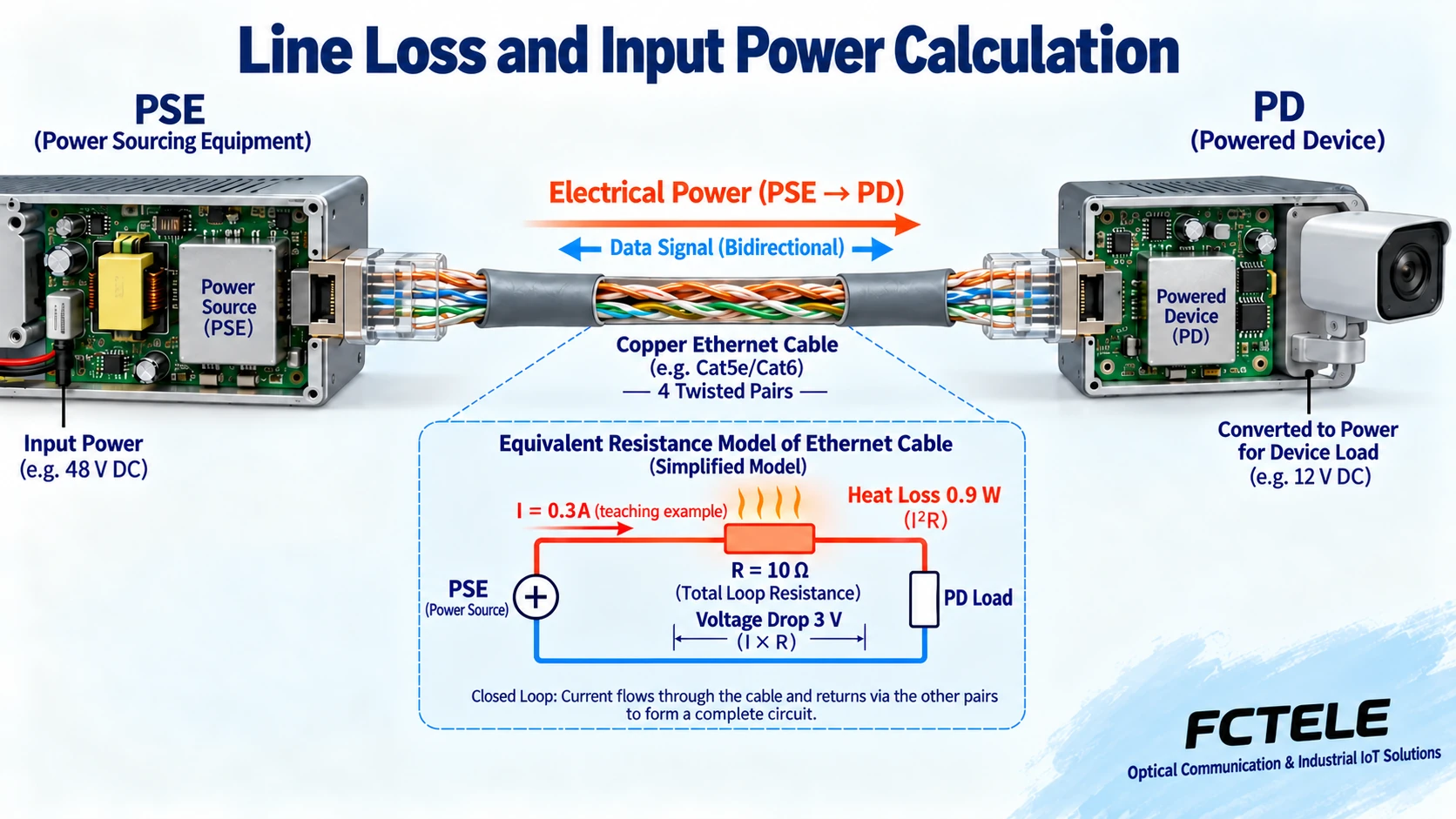
Line loss is resistance heating; voltage drop cannot be treated as power
In a simplified DC model, voltage drop is current times equivalent loop resistance, and heat loss is current squared times that resistance, that is, ΔV=I×R, P loss=I²×R. Assuming a current of 0.3 amperes and an equivalent loop resistance of 10 ohms, the voltage drop is 3 volts and the loss is 0.9 watts. The loop here is only a teaching model; real PoE has multiple conductors and wire pair arrangements, and the resistance of a single wire cannot be directly substituted.
Compliant cables, connectors, and installation quality together affect the result. A short patch cord before the port working normally does not mean a long permanent cable will also work normally. Cable bundle heating, resistance imbalance, poor contact, and ambient temperature can all change on-site performance; non-compliant conductors cannot be fixed by a larger power supply. Data transmission and power load should be verified separately, not just by checking the network port light.
Dual power supplies and fiber uplinks cannot replace capacity
Two power input locations do not automatically form two completely independent power systems. Under the planned single-path failure state, you need to confirm that the remaining power supply and device circuits can support the required load. If normal operation relies on the combined capacity of both paths, after losing one path the device may still be networked but no longer able to power all terminals. During acceptance, record separately whether communication recovers and whether terminals restart.
A fiber uplink sends data to a distant place; it does not send copper-cable PoE power along the fiber. The remote switch and its cameras still need a local power arrangement. The Feichang Technology official website 3243 details list 4 copper ports and 2 fiber ports, managed, and PoE optional capabilities, suitable for combining on-site access with fiber aggregation; the specific PoE version, input conditions, and budget must be confirmed at ordering, and the wide voltage range of an ordinary version should not be applied to a power-supply version.
How to first determine whether a nighttime disconnection is a power problem
Record when the abnormality occurs, observe whether the terminal runtime resets to zero, whether the PoE port has power-denial or overload records, and whether the data link changes. If the fault occurs only when fill light is turned on, first compare the terminal’s high-load condition, the device’s remaining budget, and the line; if multiple devices restart at the same time, also check the shared input power. A light staying on does not rule out a very short power disturbance.
During an approved maintenance window, first establish a baseline using a known compliant short cable and one known compatible terminal, then gradually increase the load or switch back to the on-site line. Change only one condition at a time and keep logs; do not restart the entire switch at the beginning. When measurement is needed, use an instrument suitable for the corresponding PoE type, and have power terminals and on-site installation handled by capable personnel.
Complete acceptance using the worst operating state
Acceptance should cover all planned terminals starting simultaneously, the actual longest line, and the expected high-load state. Record per-port allocation, whole-device budget, input power, on-site temperature, and video or wireless service results. Testing can reveal how the system performs under these conditions, but one normal run cannot be expanded into a guarantee that everything will be normal at any temperature, distance, and load.
The handover list should also explain how to recalculate when adding terminals in the future or replacing with higher-power cameras. Current power, port reservation, and whole-device capability are three different pieces of information; writing them clearly will let future maintenance determine whether the issue is capacity, cabling, or network. The answer to how many devices can be supported should come from this documented list, not just the number of ports in the switch’s name.
Documentation note: The principle diagrams have been checked against technical content and are used to explain general mechanisms; they are not product photos or measurement records. Specific interfaces, modes, and capabilities are subject to the selected model, version, and on-site verification.
Verification materials: TI PoE two-end power explanation
TI PoE interface and powered conversion materials
Cisco industrial switch PoE management materials
Feichang Technology 4 copper ports and 2 fiber ports managed industrial switch and PoE option
Translated from the Chinese technical article. Source first published: 2019-09-10. Source last revised: 2026-10-13T13:46:37+08:00. Read the Chinese source
