


A PoE switch with an integrated serial server function can complete Ethernet forwarding, power supply adapted to terminals, and network access for serial bytes in the same device. But these three paths have different rules: PoE is not serial power, network port speed is not serial rate, and supporting multiple network connections does not mean it can automatically coordinate multiple serial masters. Selection must be confirmed item by item according to the actual model, and all the advertised parameters of one device cannot be mixed onto another.
Why put switching and serial access together
Suppose a cabinet contains a network camera, an RS485 instrument, and one uplink network. A traditional solution can use a switch to connect the camera, then connect a serial server to read the instrument. An integrated device puts some functions into the same enclosure, reducing connections between devices and occupied space. This is a general solution example and does not mean all integrated switches have the same ports, power supply, or protocol functions.
Functional integration also means sharing certain resources or the scope of fault impact. When the device as a whole loses power, network forwarding and serial access may be interrupted at the same time; some management operations may affect multiple services. Whether the serial service can be restarted independently, different configurations can be saved, and different statuses can be viewed must be checked against the product and firmware. Having one fewer external device does not automatically mean the system is more reliable under all conditions.
Path one: how Ethernet data is forwarded
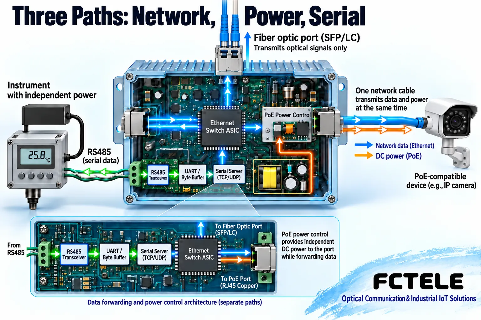
The camera organizes data into Ethernet frames, and the switch chooses the egress according to the forwarding table and related configuration. After a network frame enters the switching fabric, it may wait in a limited queue before being sent. When multiple ingress ports compete for one egress port, the egress capacity does not increase because there are more ingress ports; if input exceeds egress capacity for a long time, backlog or drops may occur. Backplane capability, network port speed, and real service throughput cannot be used interchangeably.
Network data generated by the serial channel may also use this switching network, but the instrument’s character rate, processing time, and polling method are still bottlenecks. Writing the “64Gbps” from the old text as a serial speed is inappropriate; when no corresponding model evidence is found, this number should not be retained. The nominal rate of a network interface cannot replace serial specifications or on-site measurement results.
Path two: how PoE sends power to terminals
In standard PoE, the power sourcing equipment is usually called PSE, and the powered device is called PD. An adapted power port first detects the powered device signature, then determines the power supply conditions according to the supported mechanism and provides power. Detection and power management belong to the power supply path, while Ethernet transmission and reception belong to the data path. The two can use the same network cable, but they are not the same function, and any device with an RJ45 interface cannot be treated as a PoE powered device.
When the switch uses a fiber uplink, the fiber transmits optical signals and does not send PoE power along the fiber to the far end. The far-end device needs its own adapted power supply conditions. A serial terminal also cannot be assumed to power an instrument just because it is near a PoE network port; the instrument usually still needs an independent power supply. Specific wiring and allowed power supply methods must be based on the model manual.
Why the power budget cannot be judged only by the single-port number
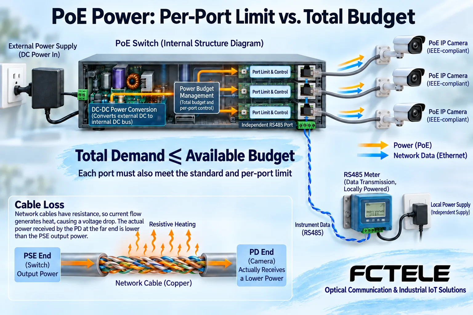
The maximum output allowed for a single port does not equal the value that all ports can reach at the same time. The whole device is also limited by the power supply, total PoE budget, temperature, and configuration conditions. The actual usable power of a powered device also involves line loss. The budget at the power supply end and the requirements of the terminal should be viewed separately, rather than directly assuming availability by multiplying the number of ports by the advertised value.
For example, suppose the design power of three terminals is ten, fifteen, and twenty watts respectively, totaling forty-five watts; actual procurement should also consider terminal startup, changes in operating mode, and the margin specified by the product. This number is only used to explain the addition method, not a Feichang Technology model specification. Port standards, the class supported by the terminal, cabling, and the whole device power supply must all match at the same time.
Path three: how serial bytes enter the network
The serial electrical transceiver circuit receives RS232, RS422, or RS485 signals, the character receiving module restores bytes according to the parameters, and the software then sends the bytes into the network connection. The interface standard, wire sequence, baud rate, and character format must match the instrument. An integrated switch will not, just because it has a switching chip, be able to directly treat serial voltage as Ethernet frames for forwarding.
Transparent mode mainly carries the original bytes; protocol conversion mode also handles the relationship between different application messages. Modbus RTU data transmitted over TCP does not automatically become Modbus TCP. During procurement, first confirm which format the software needs, then choose the device and mode that support that function. Do not mistake the Console management port for a service serial port, and do not guess the purpose from the appearance of the terminals.
How to use the corresponding Feichang Technology product information
The Feichang Technology official website has product categories for industrial Ethernet and serial data integration, and the corresponding details list combinations of network, serial, and digital input/output, and explain the product choices that PoE can support. This can serve as an entry point for finding integrated solutions, but “can support PoE” does not mean every ordering version on the page has PoE by default, nor does it prove that the seven ports, power, and protection parameters listed in the original text belong to that product.
Therefore, on-site requirements should be given to the supplier to verify the specific ordering model, power supply standard, port configuration, firmware functions, and document version. The current article does not continue to use the FCM, ONV, and other brand specifications mixed in the old text, nor does it promise unknown surge protection levels, temperatures, or ring network recovery times. General principles can help with asking questions, but specific specifications still require traceable product evidence.
Network management cannot replace serial scheduling
VLAN can divide network broadcast domains according to supported configurations, and QoS can arrange network queues according to rules during congestion, but they will not automatically allow the same RS485 bus to accommodate multiple masters asking at the same time. For multi-client access, request queuing, response matching, and permissions should be checked. Network queue scheduling and serial protocol transactions are different issues.
Redundant network paths also cannot directly bypass loop control. Protocol names, device combinations, configurations, and test conditions determine post-fault behavior, and all STP, RSTP, or other ring network capabilities cannot be uniformly written as one fixed recovery time. Serial device recovery, network recovery, and host computer service recovery also need to be tested separately.
Accept according to the three paths separately, then do combined load
First check correct power supply and installation, then separately verify Ethernet forwarding, startup of an adapted PoE terminal, and legal request-response with one serial instrument. Finally add real camera traffic, multiple terminals, and serial polling, and observe power supply alarms, network congestion, response time, and cabinet temperature rise. You cannot declare the system qualified just because the lights are on at no load.
Test power loss, unplugging the uplink, and platform restart, and record the scope affected for different services and the recovery order. Save configurations, port purposes, models, and firmware, restrict management access, and do not casually expose the serial control port to the public network. The value of reducing hardware count must be proven by the service correctness and maintenance convenience of the entire system.
Document verification: Feichang Technology industrial switching and serial combination product details, TI PoE detection and classification reference design. This article distinguishes general PoE, switching, and serial mechanisms; specific standards, power, and functions need to be checked according to the ordering model. The illustrations are general principle diagrams, not physical product cross-sections or measurements.
Translated from the Chinese technical article. Source first published: 2020-01-10. Source last revised: 2026-10-13T13:42:26+08:00. Read the Chinese source
