


Divide unreachable, dropped connections, and cross-network communication into different problems
When a physically isolated optical transceiver fails, first record the specific symptoms: the device repeatedly restarts, the optical port loses light, a certain electrical port does not light up, service throughput drops, or networks that should be separate can access each other. The first few items are mainly related to transmission and availability. The last item is related to service boundaries. Fiber does not conduct electricity, but that does not automatically prevent cross-network forwarding, and you cannot judge that the network is isolated as required just because a link light is on.
You can narrow the scope by starting with which services are affected at the same time. If all channels are interrupted at the same time, check shared power, the whole device, and the common optical path first. If only A is abnormal while B is normal, first look at the electrical ports, network cables, terminals, and mapping at both ends of A. This judgment is a troubleshooting order, not a final conclusion. A shared resource failure may also affect only part of the services first, so logs and replacement comparisons are still needed.
Preserve on-site evidence, then change one condition
Record the fault time, models and versions at both ends, port correspondence, indicator lights, device uptime, alarms, and terminal symptoms. If a managed device provides port statistics or logs, export them before operating. For devices without network management, save photos and external test records. If the fault occurs at the same time as motor start/stop, thunderstorms, or a peak traffic period, this only suggests a direction for further checking. Do not directly treat time correlation as the cause.
Each time, replace only one object known to be normal, such as a local short network cable or power supply, and note the result before and after. If you replace the power supply, optical module, patch cord, and configuration all at the same time, the service may recover, but it will be difficult to determine the real fault point. A restart may also clear transient evidence. Recording before restarting is more helpful for later review. In a production environment, arrange a maintenance window and recovery steps for operations.
When the device restarts, trace the power chain first
If the power light comes back on, uptime resets to zero, or services at both ends recover together, this suggests the device may have experienced power loss or a restart. Check the rated input, actual power supply capability, connector contact, and polarity, and check whether the upstream power supply fluctuates during the fault. Do not apply some voltage value without basis. Power specifications should be based on the manual and nameplate for the corresponding hardware version. A good optical port cannot keep a powered-off device transmitting.
For devices with dual power inputs, also check whether the two inputs are each normal, whether they share the same upstream, and the redundancy behavior of the selected model. If power is normal but the device repeatedly restarts, it may also be related to temperature, firmware, or hardware abnormalities. Keep logs and environmental records, and handle the issue according to the manufacturer’s maintenance process. Do not remove protective grounding for testing isolation, and do not perform high-voltage or surge injection tests on powered equipment yourself.
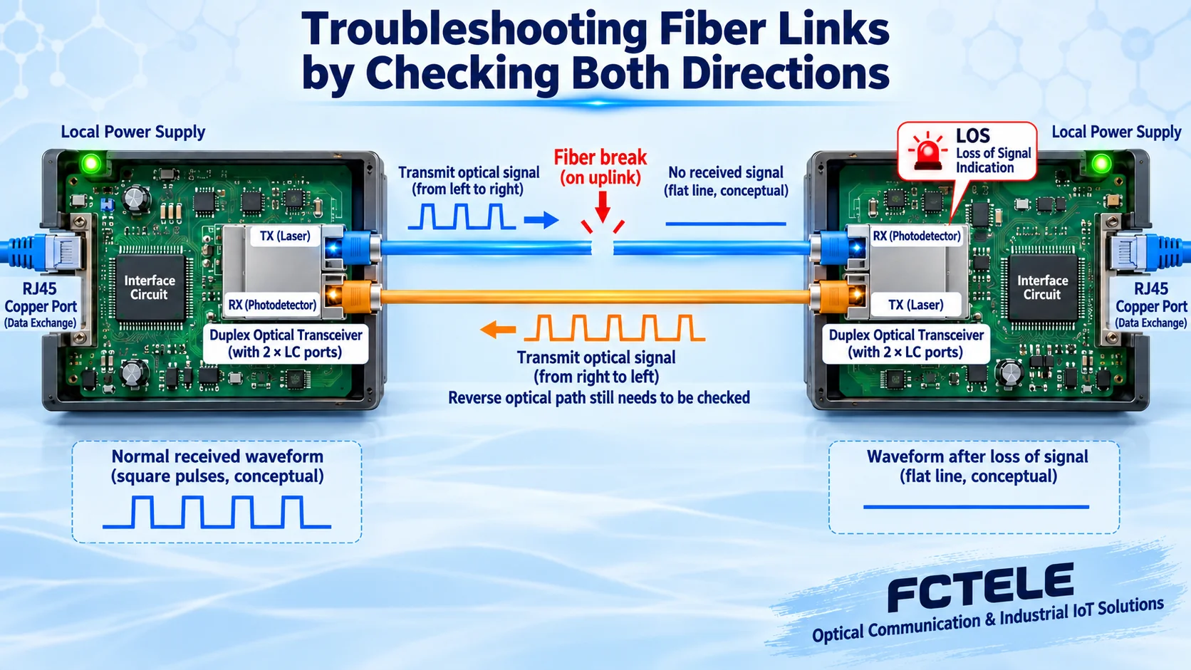
When the optical port loses light, check both directions separately
First, according to the manual, distinguish loss of light, link down, and remote power-down indications. The light meanings of different models cannot be applied to each other. In dual-fiber mode, check TX to the opposite RX and the reverse connection. In single-fiber bidirectional mode, check wavelength pairing. Then check single-mode/multimode, rate, and module compatibility conditions. Models with LFP link fault pass-through may also actively reflect an optical-side fault to the electrical port, so an electrical port light going out is not necessarily caused only by a short network cable.
Use the correct cleaning and inspection process for optical connectors. Avoid repeatedly inserting them with dirt. Choose cleaning tools according to the device requirements. Do not look directly into the optical port to judge whether there is light. First use a short patch cord and a known-good paired device for a test, then reconnect the on-site optical path section by section. When replacing a module, keep other conditions the same and record both the local and remote receive directions, so you do not miss a reverse-direction problem by testing only one end.
Whether optical power is sufficient is not the same as whether light is present
Being able to measure light does not mean the receiver can reliably recover data. You need to compare the received power with the receive range of the specific module, and also check line loss and test conditions. Too low may cause bit errors or loss of light. Too high may also exceed the receive upper limit. Digital diagnostic readings, external optical power meters, and module data should use consistent wavelength and measurement definitions. You cannot use one general threshold to judge all modules.
If a short-distance test is stable but the installed optical path is abnormal, focus on tracing connector contamination, splice loss, bending, and line matching. Even if the average received power appears normal, you should not use that to rule out intermittent contact or other abnormalities. Correlate power, alarms, and packet loss times, then decide whether a deeper line inspection is needed. Simply replacing the device with one that has higher transmit power is not a general repair method.
When a single channel is abnormal, check along the corresponding electrical port
Check item by item whether port A to remote port A matches the actual mapping, and check the rate, duplex, and network cable condition of the terminals at both ends. Do not handle an Ethernet transparent channel fault by checking serial baud rate, data bits, and stop bits. These parameters belong to different interface objects. If the link is established but services do not work, then check IP address, subnet mask, routing, terminal firewall, and application services, to avoid mistaking a terminal problem for damage to the optical transceiver.
Public information for Feichang 643 describes independent FE interfaces and dedicated time-division channels, suggesting that such products should be accepted channel by channel according to the corresponding service channels. Independent interface chips, negotiated rate, and channel capacity are related but different indicators. The information does not clearly state management, filtering, or encryption functions, so you should not assume during troubleshooting that the device has these settings. First check the actual ordered configuration and maintenance method.
When it slows down under concurrency, distinguish capacity from boundary crossing
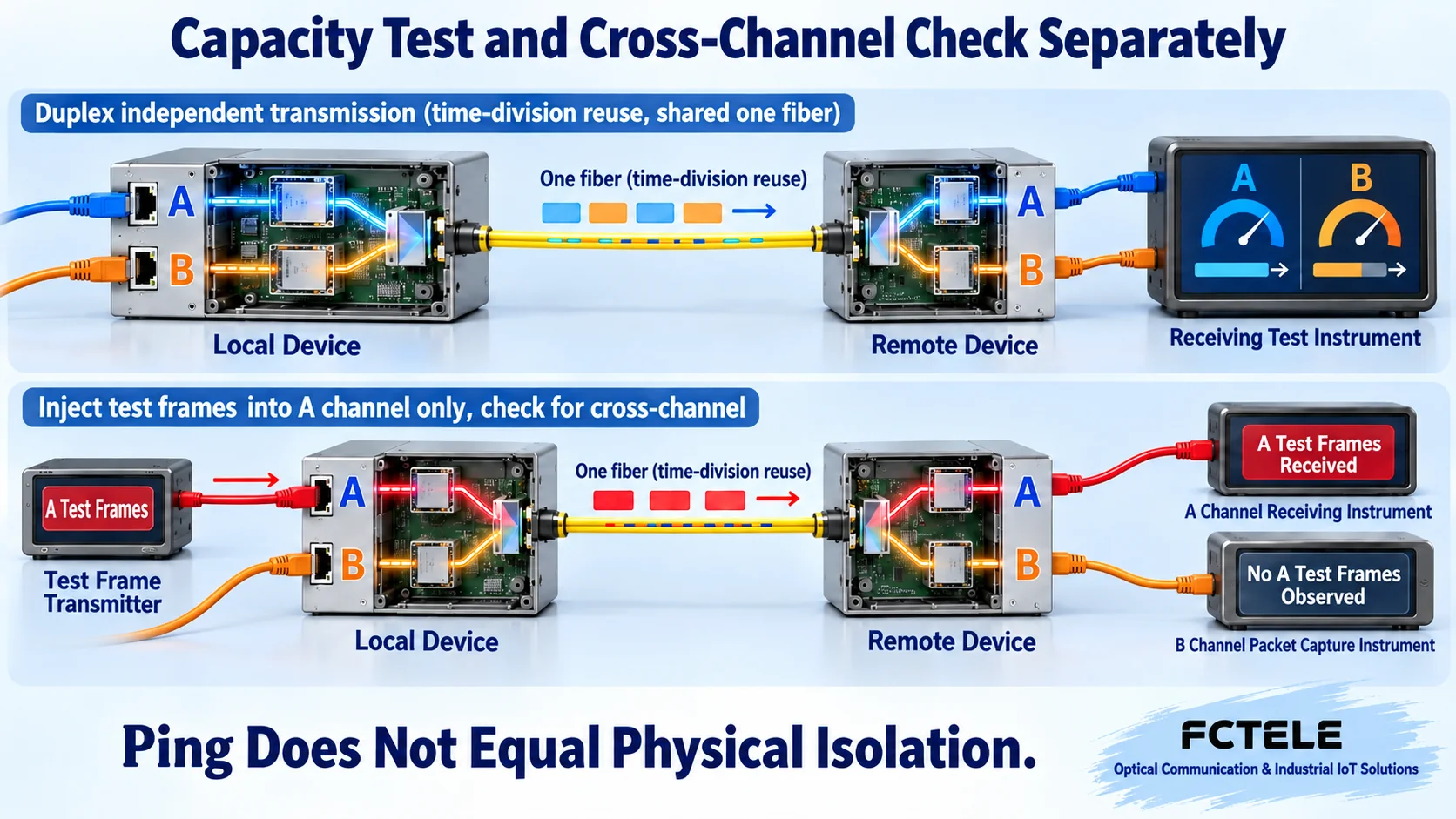
First test a single channel, then add the agreed load of other channels, and compare throughput, packet loss, and latency of each channel. The test should state frame length, direction, and duration, and check whether terminal performance and the remote switch uplink are already saturated. If two services ultimately feed into the same insufficient-capacity uplink, contention may occur outside the optical transceiver, so you cannot directly conclude that the independent transmission channel has failed.
Increased latency only indicates that some part is affected. It does not equal observing cross-channel data forwarding. Service isolation requires checking identifiable packets on channels that are forbidden to reach. Capacity problems require load and statistical evidence. CRC is used to detect transmission errors. It cannot prove that a packet comes from an authorized sender, and it cannot replace tamper-resistant authentication. An increase in error counts should be traced to link quality and cannot be directly attributed to a network attack.
If unexpected mutual access occurs, check bypass paths first
Start from the complete wiring diagram. Focus on whether the downstream connects A and B into the same broadcast domain, whether there is Layer 3 routing or temporary bridging, whether a maintenance computer with dual network cards bridges the two zones, and whether management connections cross domains. VLAN segmentation does not mean all inter-VLAN routing is forbidden. Independent service channels also cannot restrict wireless or internet connections that terminals establish separately. Checking the complete path is more reliable than just counting chips.
Keep configuration and packet capture evidence, and retest the corresponding communication, forbidden cross-communication, and broadcast handling in an independent environment. Do not connect two ports back into the service network to create a loop, and do not prove isolation by intentionally interfering with production equipment. If you suspect the device does not match the ordered architecture, give the model, version, wiring, and test records to the manufacturer for verification. Before the evidence is confirmed, do not claim that the entire system has security certification or absolute isolation.
After restoring services, also restore the original boundaries
After repairing the fault, recheck each channel correspondence, bidirectional transmission, concurrent load, and cross-communication that should be forbidden. Replacing a device or restoring configuration may change port mapping, and temporary bypasses may also be forgotten. Only a restored screen or one successful Ping cannot prove that isolation requirements and capacity requirements still hold. Temporary cross-zone connections should be cleaned up according to change records and verified again.
Maintenance records should save the fault cause, replaced objects, configuration differences, measurement conditions, and recovery results, and include repeatable phenomena in later observation. Arrange cleaning and heat dissipation, power inspection, and optical cable status according to site conditions and the manual. Do not understand “maintenance-free” as never needing inspection. Independent service channels, optical cables, and chassis all need maintenance. Reliable operation comes from clear boundaries and explainable evidence.
Information note: The principle diagrams have been checked against technical content and are used to explain general mechanisms. They are not product photos or actual measurement records. Specific interfaces, modes, and capabilities are subject to the selected model, version, and on-site verification.
Verification materials: Feichang 1–4 channel 100M physically isolated transceiver 643
NIST: OT Security Guide SP800-82r3
Cisco: LAN Switching Troubleshooting
Translated from the Chinese technical article. Source first published: 2024-05-07. Source last revised: 2026-10-13T13:28:52+08:00. Read the Chinese source
