


First distinguish auxiliary communication from protection services
A grid site may have on-duty telephones, dispatching voice, equipment status, and dedicated protection communication, and their importance and technical requirements are not the same. PCM multiplexing equipment can connect the telephone, audio, and low-speed data modules it supports, but you cannot assume that just because the equipment is used in a substation it naturally meets all teleprotection channel conditions. The service system owner should first explain the interfaces, continuity, and response requirements, and then the transmission plan is decided.
This article discusses general ideas for PCM auxiliary communication access and does not claim that a particular model has completed a specific grid project or obtained unverified certification. Dedicated remote protection command transmission has its own performance and testing requirements, and IEC 60834-1 can serve as a standard entry point for understanding this type of system. Actual protection services must be verified according to applicable specifications and engineering design, and the fact that an ordinary telephone can get through cannot be used as evidence that a protection channel is qualified.
Turn requirements into interfaces and channels
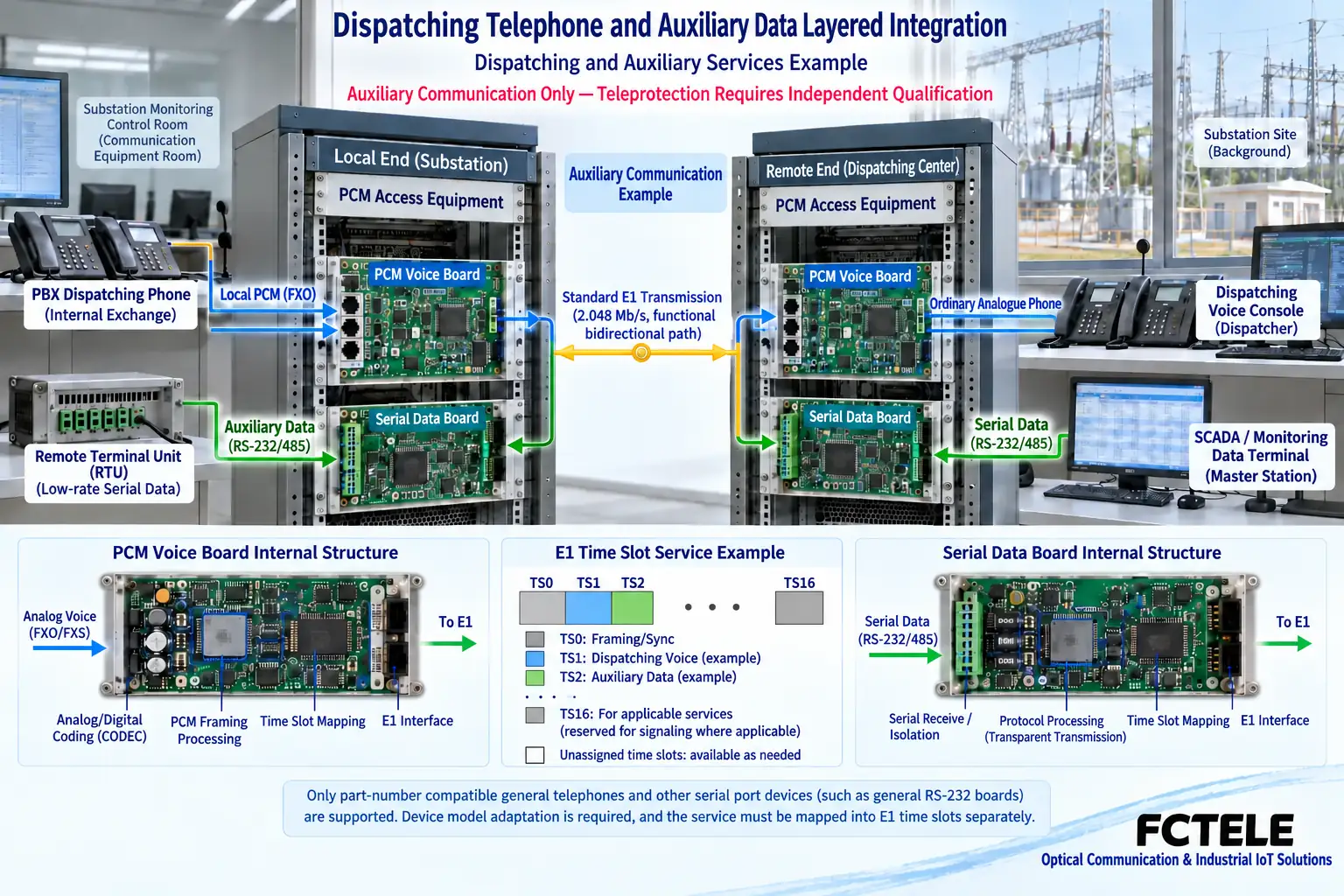
If a site telephone extends an existing switch subscriber line, you need to check the corresponding roles such as local FXO and remote FXS. Four-wire audio also requires confirming direction, impedance, and level; auxiliary serial data requires checking electrical standards such as RS232 and RS485 and the communication settings. These requirements should be written into the interface table at both ends, not just listed as “several voice and data channels.” Management network ports and console interfaces also cannot be assumed by default to be user service ports that can be transmitted across the trunk.
Whether one integrated chassis can support multiple interfaces depends on the actual modules and their configuration. Telephone, audio, and data boards may occupy different resources, and this should be checked against the model documentation. Access equipment is only responsible for interface adaptation and channel organization within its supported scope; it cannot automatically interpret the application protocols of different systems, and it certainly cannot arbitrarily change the meaning of service data without configuring the corresponding gateway.
E1 bearer requires consistent time slot arrangement
Framed E1 organizes time slots at a fixed pace, and both ends extract each service according to the same agreement. A common E1 frame has 32 time slots and a line rate of 2.048 Mbit/s, but synchronization and signaling occupancy affect the available resources. You cannot look only at the total line rate and count all time slots as effective user services; how telephone and data are arranged should be determined by the actual framing, signaling, and module mechanisms.
The site channel table should list the source port, module position, E1 number, channel mapping, and remote destination. In this way, when a voice or status data channel is abnormal, troubleshooting can follow the corresponding relationship without changing the entire chassis at the same time. If time slot cross-connect functionality is available, the mapping before and after adjustment should also be saved. Normal line synchronization only confirms part of the trunk status; correct services still need to be verified on the real interfaces at both ends.
Clock planning must cover the complete link
An E1 network needs coordinated timing. Among the line provided by the operator, the in-station transmission equipment, and the PCM equipment at both ends, the clock provision and recovery relationships should be clarified to avoid master-slave conflicts or timing loops. Setting each device clock to the same name does not show that the entire system is correctly synchronized; likewise, “local internal, remote line” is not a universal rule for all grid access schemes.
If primary and backup paths exist, the timing plan should explain where the clock is recovered from after switching and how to handle an abnormal backup path. During stable operation, observe alarms and bit errors, and check for intermittent slip or voice interruption under actual service conditions. For the delay and continuity specified by the service, corresponding measurement methods and acceptance indicators should be used, and the fixed transmission pace of time slots cannot be directly equated with an end-to-end performance guarantee.
Two trunks may still share a failure point
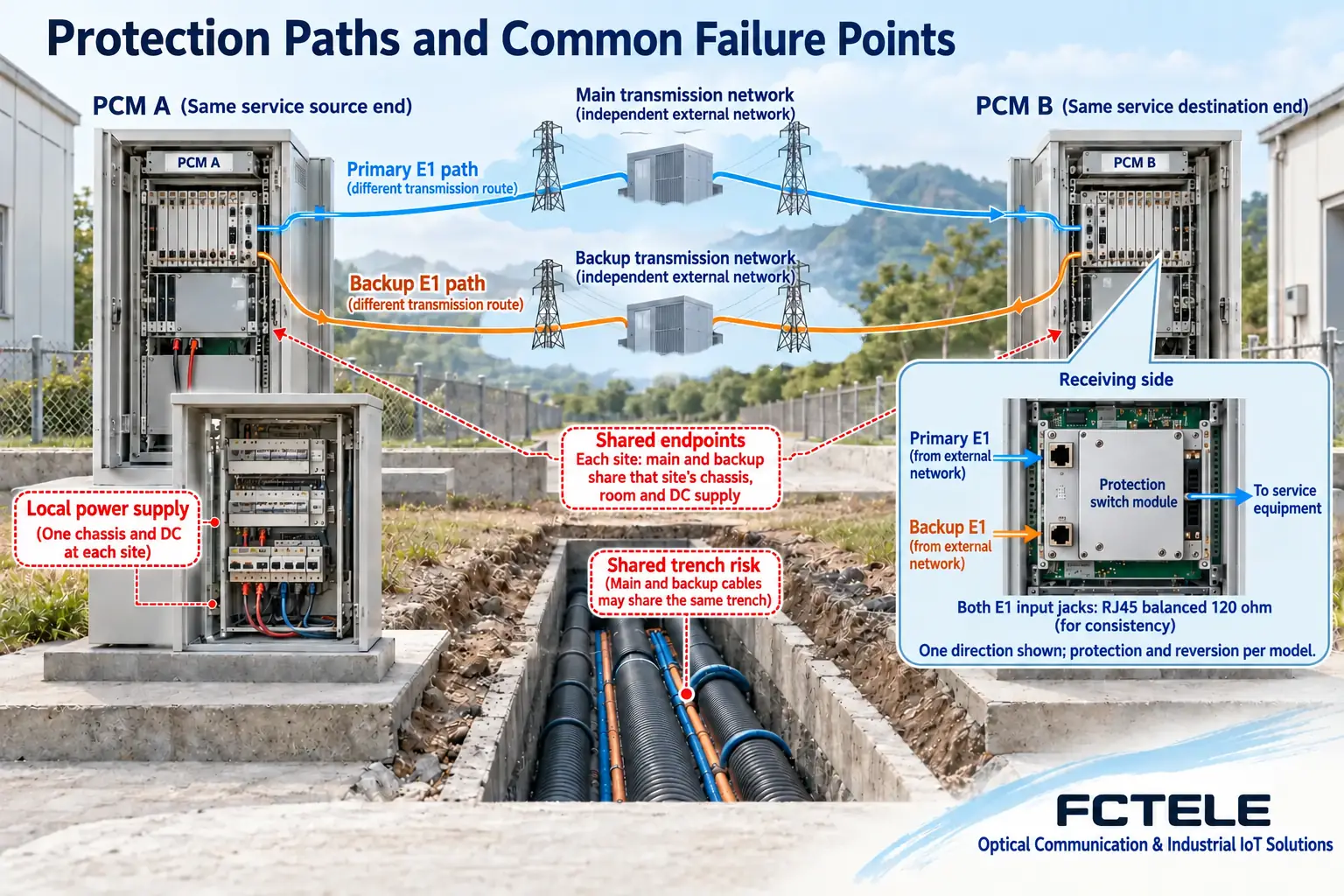
Equipment that supports dual E1 protection can select between primary and backup paths according to the model mechanism, but if the two lines share one transmission chassis, one set of power supplies, or the same vulnerable path segment, one fault may still affect both lines at the same time. The network diagram should mark shared equipment and power supply conditions, and clarify whether this protection covers trunk interruption, transmission equipment abnormality, or other specified events, rather than vaguely writing “system redundancy.”
The public product documentation for Feichang Technology FC2C-E1O30/FC2C-E1S30 provides an entry point for checking models with dual E1 protection, and the specific trigger and recovery strategies still need to be checked in the configuration and verified on site. Adding a backup E1 does not automatically protect telephone boards, local chassis power failure, or upstream switch faults. Protection testing should also observe real service interruption and recovery, and port status changes cannot be directly promoted as lossless switching in all cases.
Consider the electrical environment and safety isolation separately
The power supply, grounding, outdoor cabling, and electromagnetic environment of a grid site need to be handled according to the site design and product installation requirements. A fiber optic intermediate link does not conduct current, but that does not mean the entire chassis has no other metal connections; telephone, power, serial, and management lines may still bring different coupling paths. Fiber optic transmission also cannot be directly equated with network security physical isolation or immunity to all lightning effects.
Whether equipment has a certain surge tolerance or protection rating should have corresponding model documentation and test evidence, and cannot be inferred from the name “industrial” or “grid.” Matters involving protective grounding, power abnormalities, and damaged boards should be handled by qualified personnel according to the on-site maintenance system. Service network management access should independently manage accounts and access permissions, and configuration interfaces should not be exposed to unplanned networks.
Accept the line layer and service layer separately
At the line layer, check cables, transmit and receive direction, electrical specifications, framing, clock, and alarms; at the service layer, check channel destinations, interface parameters, and the actual service process. Telephone testing includes call setup, two-way voice, and release; for auxiliary serial ports, you can first use known test samples to check bytes and order, and then connect real equipment to verify status and interaction. Only by recording the two layers separately can you know what a single “normal” actually proves.
Within the approved test window, further cover the agreed concurrent load, trunk abnormality, and recovery. Loopback should note the location and test scope, confirm exit after testing, and re-verify user services. For dedicated protection communication, independent acceptance should be performed by the corresponding professionals, and ordinary PCM channel test results cannot replace system performance verification of protection command transmission.
Use delivery documentation to support later maintenance
For example, if a site needs to extend four on-duty extensions and one auxiliary status serial port, first check the interface roles, module support, and trunk resources, and then arrange the channels at both ends. This is a requirements organization example, not a default product configuration. If there is also dedicated protection service, its equipment, bearer path, and acceptance requirements should be marked separately so that maintenance personnel can clearly understand the different responsibility scopes of the two types of lines.
At delivery, save the model version, board list, channel mapping, clock diagram, primary/backup definition, and actual test records. When modifying or expanding, first check the existing trunk resources and shared failure points, and then decide whether to add modules, trunks, or transmission equipment. The role of PCM equipment is to complete aggregation and extension within a clearly defined interface scope; only by distinguishing service nature and verification conditions can equipment functions be prevented from being overextended to critical communication tasks for which they are not suitable.
Documentation note: The principle diagrams have been checked for technical content and are used to explain general mechanisms; they are not actual product photos or measured records. Specific interfaces, modes, and capabilities are subject to the selected model, version, and on-site verification.
Verification references: ITU-T G.704: Frame structures for digital interfaces
ITU-T G.703: Electrical characteristics of digital interfaces
IEC 60834-1: Teleprotection command transmission systems
Feichang Technology E1 PCM multiplexing equipment
FC2C-E1O30/FC2C-E1S30 product documentation
Translated from the Chinese technical article. Source first published: 2021-09-29. Source last revised: 2026-10-13T13:23:07+08:00. Read the Chinese source
