


The job of an RS485 isolation circuit is to let serial port information cross an insulation barrier, while reducing the problems caused by directly connecting the ground potentials on both sides. It does not turn external copper wires into fiber optics, and it does not make the interface able to withstand any voltage. To understand it, you need to look at signals, power and port protection separately: the fact that a signal can cross over does not mean the power supply is already isolated; and having an isolation device does not mean all surges can be blocked. This article discusses general circuit mechanisms and does not provide a finished circuit that can be copied directly.
1. First look at the electrical relationships of a non-isolated interface
The controller’s UART transmit logic enters the RS485 driver, and the driver produces a differential signal through two lines; in the receive direction, a differential receiver restores the line state into logic that the controller can read. In an ordinary non-isolated design, the controller and the transceiver often share a power reference. If the power grounds, cable references or enclosure connections of the devices at both ends form an unsuitable potential relationship, the common-mode conditions seen by the receiver may exceed the allowed range.
A differential receiver compares the difference between the two lines, which helps suppress part of the interference that is superimposed in common, but it does not make the voltage of each line relative to the local reference irrelevant. The fact that two devices can transmit bytes does not prove that they can work under any ground potential difference. When crossing cabinets, crossing areas, or being near strong electrical equipment, isolation, reference lines and protection measures need to be evaluated according to the system environment, rather than omitting electrical design just because of the phrase “485 is resistant to interference.”
2. How signal isolation transmits digital states
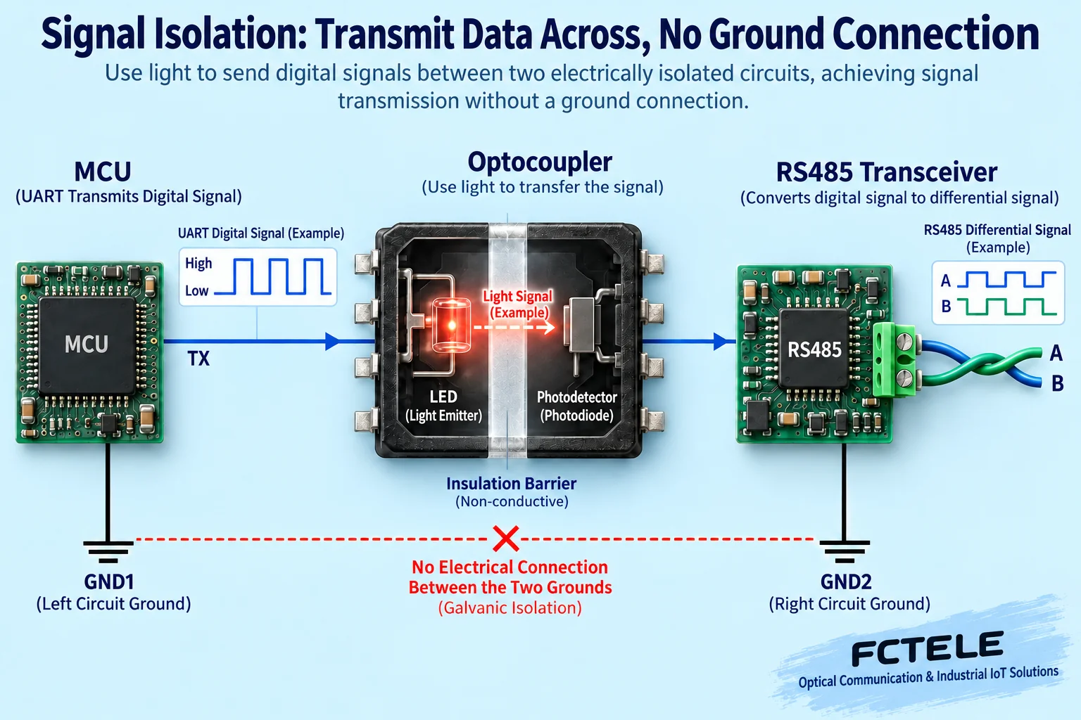
An optocoupler is a common isolation device: current on the input side drives an internal light-emitting device, and a photosensitive device on the output side receives the change in light, with no normal DC signal conduction between the two sides. What it transmits is logic information, not the original copper wire current sent across. When used for a UART interface, transmit, receive and direction control may each need a signal channel across the barrier; you cannot assume that a complete half-duplex circuit needs only one optocoupler just because only one transmit arrow is drawn.
Magnetically coupled or capacitively coupled digital isolators can also carry information across, but their principles and parameters are different, and they cannot all be called optocoupler isolation. An integrated isolated transceiver may put digital isolation and the RS485 line circuit into one chip. When designing, check the logic levels, channel directions, delay, default states and common-mode transient immunity. The fact that the isolation device is fast enough does not mean the entire bus can reach the same rate at any cable length.
3. Why an independent isolated power supply is also needed
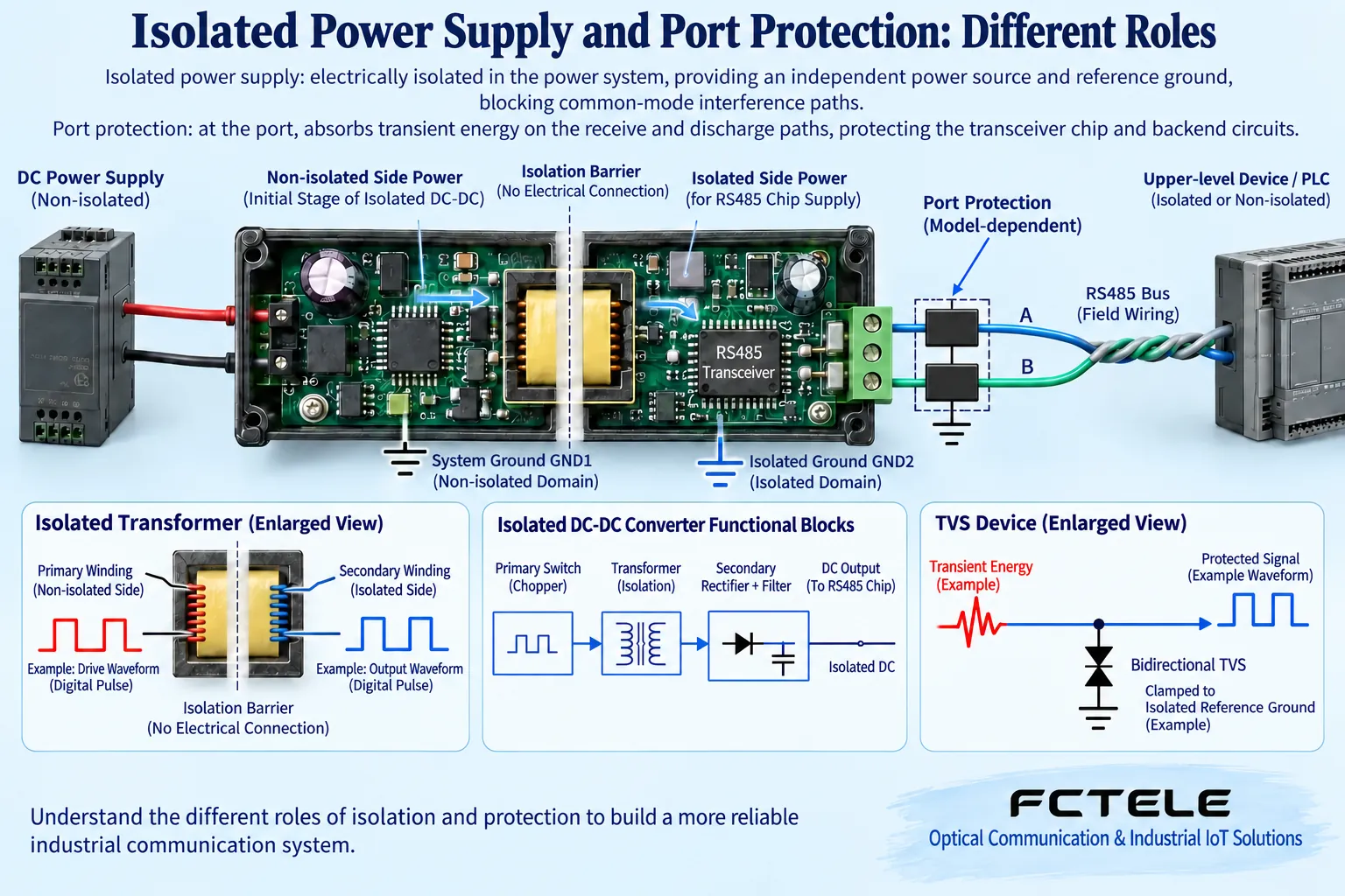
If the signal is already isolated, but the two sides are connected again through a non-isolated power ground, the DC path that was originally meant to be cut still exists. A common complete isolated interface therefore lets the controller side and the bus side use independent power references. An isolated DC/DC transfers energy through the magnetic coupling of a transformer; the primary and secondary windings have no normal DC connection, and the secondary power supply serves the transceiver on the isolated side.
Some chips integrate signal isolation but not an isolated power supply, while some solutions provide both; you cannot guess the function just from the package name. Taking TI ISO1430 documentation as an example, it can be used to check an integrated isolated transceiver and the power supply boundary; the actual required external power supply should be checked in the corresponding version. The isolation capability of a third-party device only describes that device itself; it does not prove that any Feichang Technology model uses this chip, and even less does it prove that a complete unit already meets the same safety level.
4. The isolation barrier cannot be bypassed by other connections
Creepage distance, clearance, connectors and wiring on the board affect the actual isolation boundary; you cannot look only at the nominal withstand voltage of the isolation chip. Shielding, debugging cables, enclosure connections, oscilloscope ground leads and another power supply may all form paths that bypass the barrier. Normal wiring and maintenance test wiring should be drawn into the system diagram together, to check where protective grounding is needed, where the signal reference is, and where direct connection is allowed or not allowed.
Isolation withstand voltage, continuous working voltage and transient specifications are not the same value, and withstand voltage cannot be used to infer that the data terminals are allowed to be connected directly to strong electrical power. Isolation usually refers to the insulation relationship under specified conditions, and the receiver port still has its own electrical limits. During maintenance, do not casually bridge the grounds on both sides just to “make the references consistent,” and do not treat an instrument ground clip as an ordinary probe; live measurement should use a suitable method according to the actual potential and the instrument’s rating.
5. Surge protection and isolation have different roles
Devices such as TVS help reduce the stress borne by the port by limiting transient voltage and diverting current; isolation devices instead change the electrical conduction boundary. Protection devices must be coordinated with the transceiver’s allowed range, the cable, grounding and the expected transient. Selection also needs to consider the effect of device capacitance on high-speed edges, clamping conditions and energy withstand capability. A fixed TVS voltage, series resistance or power value cannot be applied directly to all interfaces.
Older articles treated ordinary Zener diodes or resistors as general protection substitutes, which easily ignores fault energy and dynamic behavior. This article does not provide such simplified replacement suggestions. Even if a device passes one kind of electrostatic test, it does not mean it can withstand all lightning strikes, continuous mistaken power connection, or surges with different waveforms. The corresponding test conditions and complete unit reports should be requested, and the protection level should be confirmed according to the project environment, not ended with the two words “lightning protection.”
6. How specific products connect with circuit verification
The Feichang Technology FCC-RD datasheet describes active isolation conversion, high-speed optocoupler signal isolation and isolated DC/DC power supply, and can be used to understand how an external RS232 to RS485/422 converter establishes an electrical boundary. These features belong to that model’s documentation and do not mean that the diagrams in this article are its actual PCB. Although pure isolated repeaters, MCU interface boards and fiber optic converters may share some principles, their connection objects and power supply conditions still need to be checked separately.
First verify both directions of the serial port, driver release and power-on default states on a suitable bench, then check behavior when idle, disconnected and reset. Measurement and insulation tests require the corresponding equipment and personnel, and high voltage must not be applied to terminals by yourself during ordinary commissioning. Finally record the isolation domain, power supply paths, signal channels, port protection and service tests; only by keeping the main text, wiring diagram and actual ordered version consistent can isolation change from a promotional word into a reviewable design condition.
Source verification:TI RS485 Design Guide;TI idle fail-safe note;TI isolated transceiver documentation (general principles);Feichang Technology FCC-RD datasheet;Feichang Technology FC2P-D/Q/R ring network product documentation. The illustrations explain general mechanisms and and are not actual photos, actual PCBs or measured waveforms of the corresponding products. Specific parameters and capabilities are subject to the corresponding model, version and delivery documentation.
Translated from the Chinese technical article. Source first published: 2021-06-09. Source last revised: 2026-10-13T12:33:29+08:00. Read the Chinese source
