


When an RS-485 hub drops stations, times out, or shows checksum errors, first divide the problem into power, wiring, electrical signal detection, and protocol timing, then compare section by section. It is not an Ethernet HUB, so do not troubleshoot with crossover cables, IPX, or NetBEUI. The transmit and receive lights only show that some circuits are active; they cannot prove that instrument addresses are correct or that returned data is valid.
1. First record the symptoms and scope of impact
Ask clearly whether all nodes are offline, or only one branch or one instrument is abnormal; whether the fault appears with newly added nodes, faster polling, inverter operation, or environmental changes. Record the model, interface version, power supply method, master serial port settings, and nodes on each branch, then save a time-stamped message log. Only by looking at the site symptoms together with the historical baseline can you determine which boundary the fault occurs at.
A timeout seen by the master means that no valid response was received within the waiting window. The cause may be that the request did not arrive, the slave did not process it, the response did not return, the format was wrong, or the window was too short. A checksum error means that the received message did not pass the check, which may come from interference, collision, or a sampling format problem. Do not conclude that the cable is broken based only on one software prompt, and do not mistake the absence of an IP address for a transparent HUB not working.
2. When everything is abnormal, check the common path first
The common path includes the power supply, master interface, uplink cable, and common configuration. Check the power polarity and range against the nameplate and ordering information, and observe whether the power supply is stable when the load changes; input conditions may differ between different models in the same series, so do not copy the parameters from an old article. The power light being on only indicates that some power supply conditions exist; it cannot replace checking the power input and circuit operating state.
When shutdown is permitted, keep one short branch and one known-good instrument to restore a minimal network. If it still fails, first confirm the master interface and serial port format, then compare the functions of the uplink and downlink terminals. Two-wire and four-wire RS-485, RS-422, and RS-232 are wired differently; A/B naming may also differ by manufacturer, so you need to compare by function and must not apply Ethernet cable crossover wiring.
3. There are still several steps between a level change and correct bytes
The receiver first judges the differential voltage of A/B, the serial port then assembles bytes according to bit timing, and the protocol then checks the address, length, and checksum. Noise may cause an error at a certain decision point, and parameter mismatch may prevent even a stable level from being sampled correctly. Testing should distinguish three layers: electrical waveform, serial characters, and protocol messages. Do not treat a blinking light or garbled text in a terminal window as successful communication.
When differential waveforms need to be measured, personnel with the proper conditions should use suitable differential or isolated measurement methods, to avoid a common grounded probe shorting different electrical domains. The levels and timing in the figures only explain the mechanism; they are not on-site measurements. General maintenance personnel can first do terminal, power, parameter, and single-node comparisons, and clearly hand the boundaries that require measurement to professionals, rather than blindly connecting instruments.
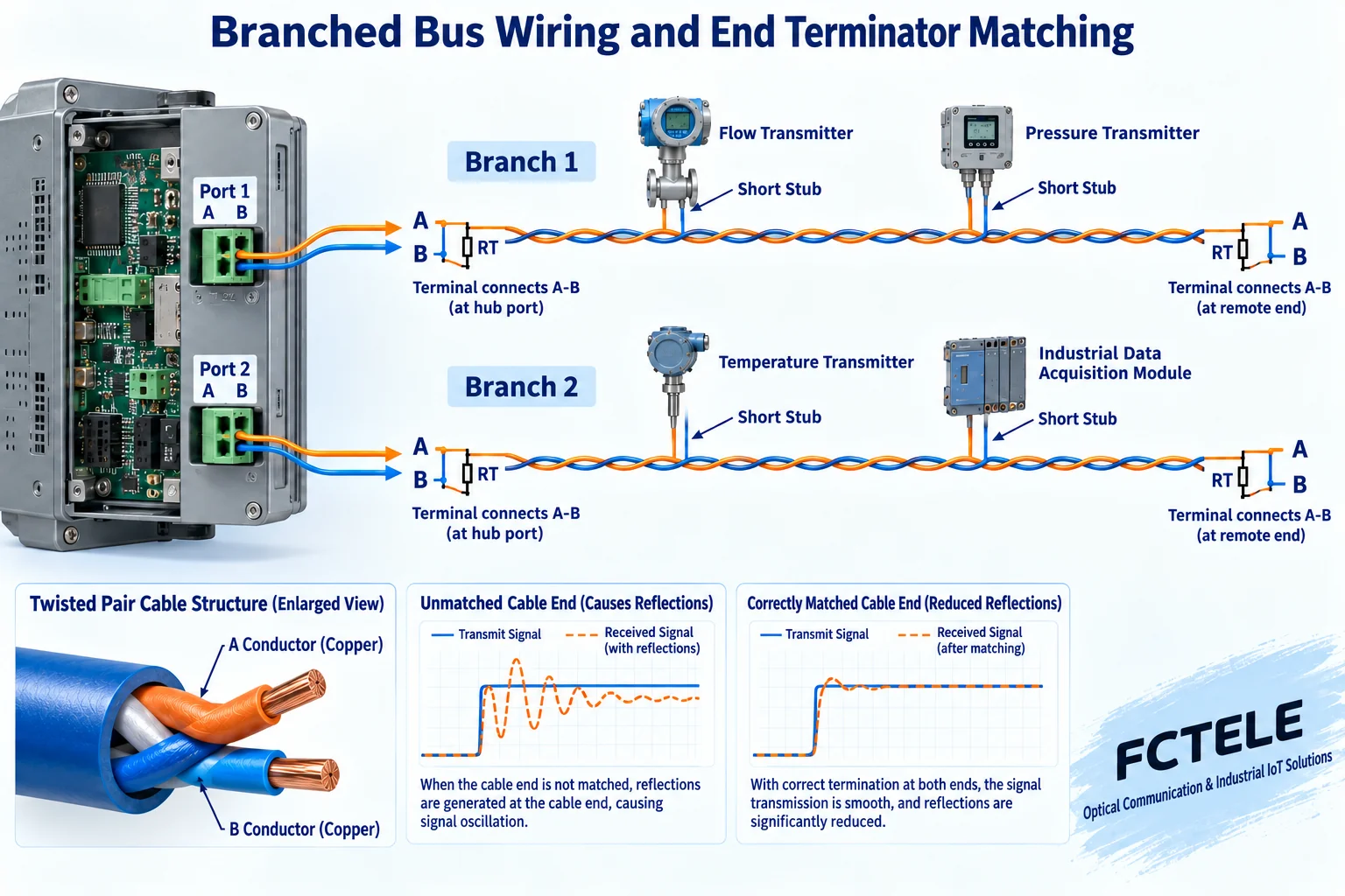
4. When one branch is abnormal, check the conditions of that section
Check for loose terminals, A/B miswiring, damage or moisture, node power, and the default address of newly added devices. Check the baud rate, data bits, parity, and stop bits one by one, and confirm that the slave addresses visible to the same master are unique. Devices with the same address on two branches may respond at the same time, and the error symptoms may not necessarily be concentrated on only one of the lines. Recovery after isolation is only a locating clue and cannot by itself prove hardware damage.
Each downlink branch is still designed as a bus, with short node drop lines on a long trunk, and termination arranged at the two ends of that segment. Check whether too many terminators have been added externally, whether the far-end terminator is missing, and whether the bias and built-in termination settings match the manual. Do not try your luck by continuously adding terminators, increasing voltage, or swapping ports; change only one condition at a time and keep the result.
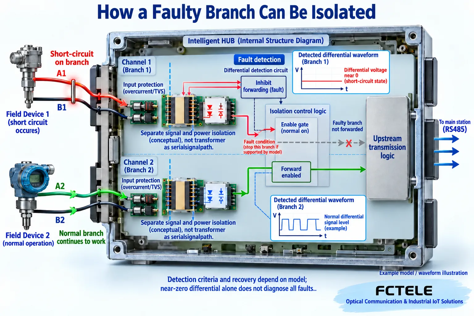
5. Ordinary isolation and automatic fault disconnection are different
Electrical isolation reduces direct conductive coupling, but an abnormal branch may still send a continuous level or erroneous data into the internal direction logic. Whether A/B short circuits are detected, whether forwarding on that path is stopped, and whether a fault is indicated are dedicated protection mechanisms, and you cannot assume they are present just because the device says “isolated.” The power, signal, and reference ground boundaries on the control side and each field side should also be confirmed according to the model.
The Feichang FC-D8JM product description lists per-channel A/B short-circuit and abnormal data detection, automatic isolation of faulty channels, and status indication, making it suitable for projects that need to reduce the scope of fault impact. After identifying a fault, you still need to check the cable, terminals, and nodes of the corresponding branch and verify the recovery process. A protection action is not the same as repairing the on-site wiring, nor can it replace the master’s timeout and retry control for faulty nodes.
6. Narrow the scope in comparison order
During a maintenance window, first save the communication baseline of a normal branch, then disconnect the abnormal branch by area for comparison, and note whether disconnection changes the termination conditions. If the master recovers, perform an independent short-cable and single-node test on that area, then gradually restore cables and nodes. If it recovers after replacing with a known-good cable, continue checking the terminals, routing, and shielding of the original cable, rather than directly replacing the HUB.
If only fast polling fails, check response waiting, direction release, and frame interval; if it fails only after adding nodes, first check address duplication, load, and time budget; if it is abnormal only when a motor starts, focus on routing, common-mode conditions, and power supply changes. These correlations are a starting point for troubleshooting, not a final conclusion, and need to be verified with repeatable records before and after one change.
7. After recovery, perform real service acceptance testing
One successful test message only shows that communication is possible at that time point and with that parameter combination. After restoring all branches, continuously record correct responses, checksum errors, timeouts, retries, and refresh cycles using the actual message length and access frequency. Check whether faulty nodes slow down other devices due to long waits, and whether application registers and application updates are also normal when the indicator lights are normal.
Dedicated fault injection can only be performed on a low-voltage test branch that is permitted by the manufacturer and isolated from production impact. It is strictly forbidden to connect mains power to communication terminals to verify isolation. Keep the model version, wiring photos, parameters, termination positions, and repair measures, and explain at handover which conditions have been verified. A good troubleshooting result is not only “it works now,” but should also explain which section the fault occurred in, what comparison was used to locate it, and how to recheck after recovery.
Sources:Feichang RS485 hub product category;Feichang FCC-D4JM four-channel product description;Feichang FCC-D4M buffered multi-master product description;Feichang FCC-D8J eight-channel specification;Feichang FC-D8JM intelligent eight-channel product description;TI RS485 Design Guide;Modbus Serial Line specification entry. The diagrams explain general mechanisms; they are not actual PCB, product physical object, measured waveform, or certification document; model capabilities are subject to the corresponding materials and delivery version.
Translated from the Chinese technical article. Source first published: 2021-10-29. Source last revised: 2026-10-13T12:33:29+08:00. Read the Chinese source
