


Just by the two letters “OA,” you cannot determine what a light on a PDH fiber transmission unit actually means, nor can you directly assume it is an optical amplifier indicator or that “a lit light means normal.” OA is not a light name that can be uniformly applied across manufacturers and models. The correct approach is to check the device model, panel, and corresponding manual, then place the observed state into the context of optical reception, E1 interfaces, and the service link to make a judgment. When model information is missing, this boundary should be clearly preserved.
Why one abbreviation cannot replace the manual
The name of an indicator light is determined by the device design. Light on, light off, slow flashing, and fast flashing may also represent different states. Similar abbreviations may have completely different meanings on another type of device. Seeing a mark containing the letter A and inferring it is an amplifier, or seeing green and assuming service is normal, can both mislead troubleshooting. In particular, you must not directly move module names from SDH or large optical transmission platforms onto the panel of an ordinary PDH fiber transmission unit.
You should first record the complete model, the paired devices at both ends, a photo of the panel, the indicator states, and the time they appeared, then check the corresponding version of the documentation. If the official website only has a product overview and no indicator meaning table, you should confirm with the manufacturer and not fill the gap with guesses. What is discussed here is a general judgment method, not inventing an OA definition for an unknown device when information is missing. Only after readers obtain the correct manual can they match the link ideas in this article with the actual light meanings.
What a PDH fiber transmission unit mainly carries
Common PDH fiber transmission units are used to transmit one or more E1 and other digital services over an optical link to the other end. The transmitting end receives an electrical signal that meets the requirements, performs corresponding conditioning and multiplexing, and then outputs it through an optical transmitter; the receiving end converts the optical signal into an electrical signal, recovers the data and timing, and then separates out the corresponding service interfaces. It is not a universal device that can convert any plug it sees.
PDH is often called plesiochronous digital hierarchy in Chinese, and it involves digital tributaries and corresponding multiplexing relationships. Whether an actual product provides Ethernet, voice, or other additional services should be based on the model configuration. The definition of an ordinary E1 port, optical port parameters, and external application requirements need to be checked separately. When a service problem occurs, the panel alarm is only one observation point; it will not automatically tell you all internal and external causes.
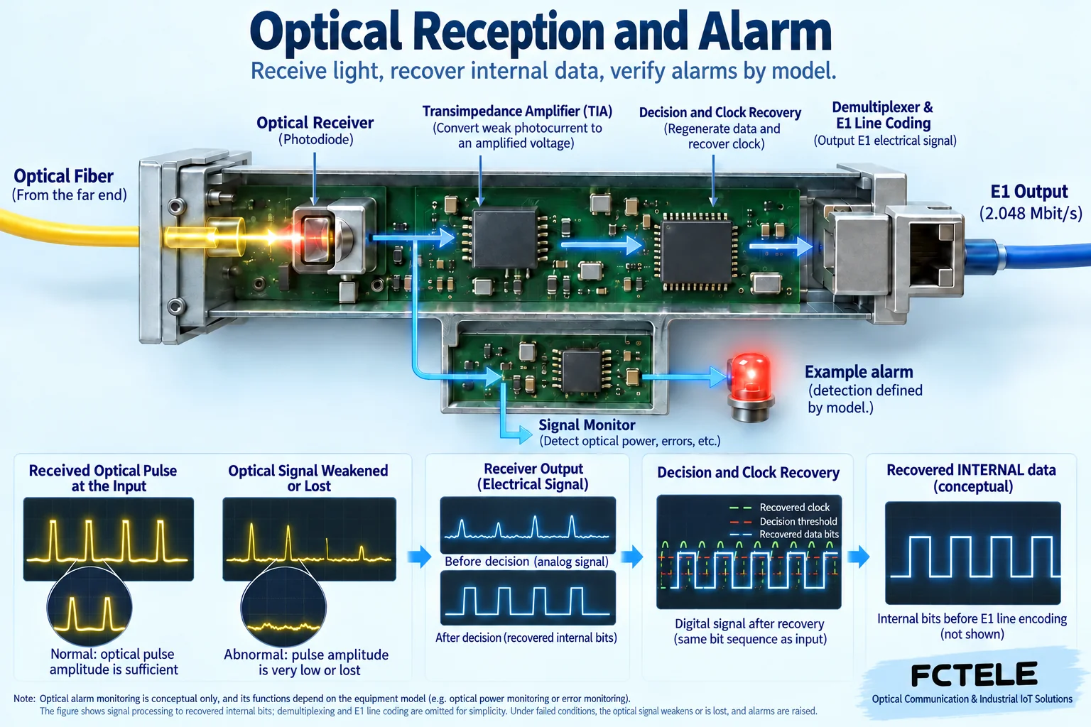
Why the optical receiving circuit needs decision and clock
After the modulated light in the optical fiber reaches the receiver, the photodetector converts changes in light into changes in electricity, and then amplification and processing circuits form a signal that can be judged. Digital reception needs to determine which moments represent zero and which represent one, and recover a suitable sampling rhythm. The electrical signal amplification here is part of the receiving circuit, and you cannot therefore conclude that the device necessarily contains an optical amplifier in the communications system sense.
When the optical signal is too weak, the waveform quality deteriorates, or the timing cannot be reliably recovered, the digital output may have errors or be lost. Some monitoring circuits generate alarms based on this, but the specific detection target and threshold are determined by the device design. An alarm reflects an observed condition and is not equivalent to directly identifying the root cause. For example, failure to receive a normal signal may be caused by the line, the far-end transmission, the pairing method, or the local interface.
Why receiving light does not necessarily mean receiving correct data
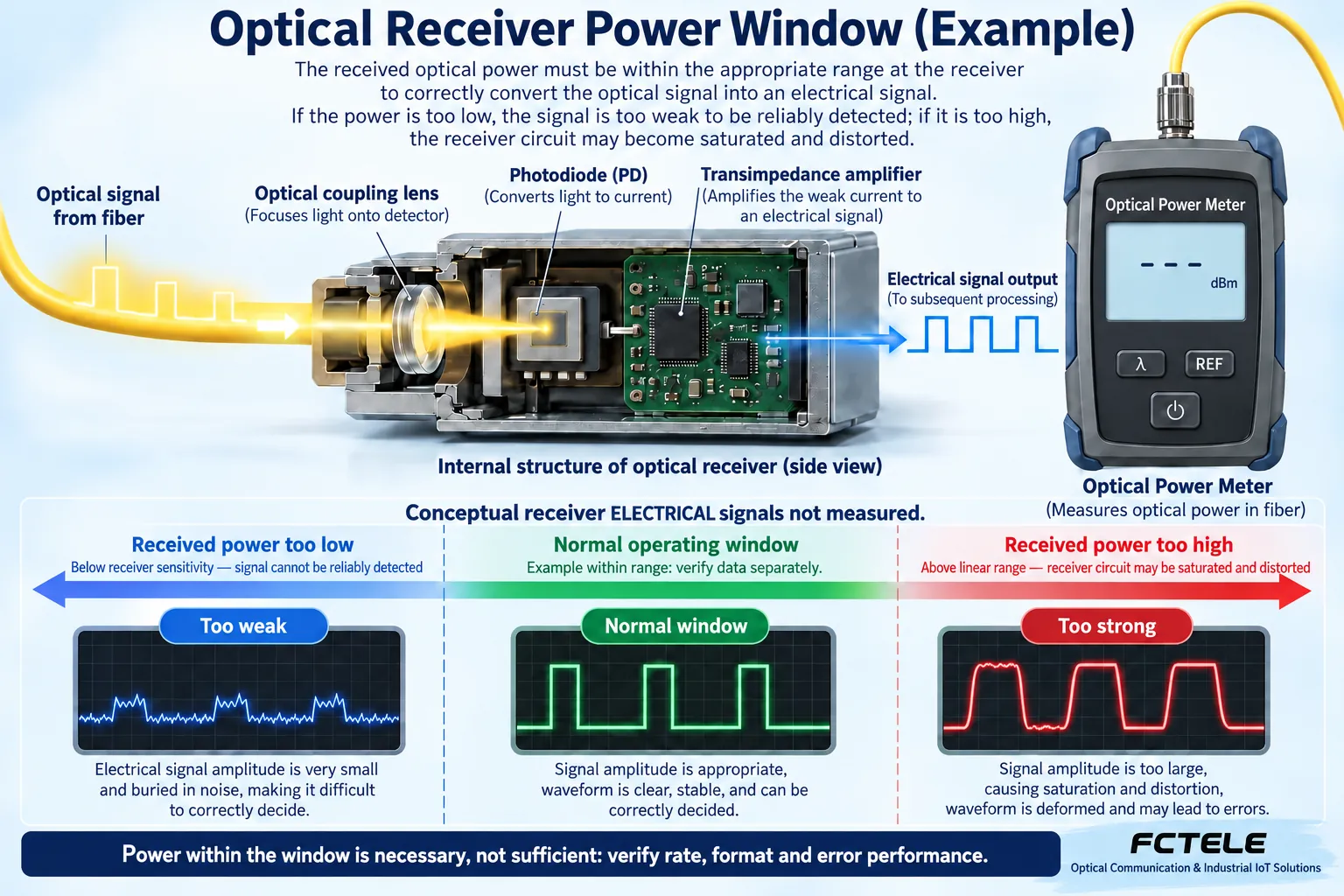
A receiver has an applicable optical power range. Below the required condition, the signal may be difficult to distinguish reliably; above the receiving capability, it may also be distorted due to overload. You cannot assume that stronger light is always better, nor can you assume that measuring a value with an optical power meter proves the service is normal. The measurement result must be compared with the specifications for the corresponding interface and wavelength conditions.
Besides power, you also need to confirm the rate, wavelength, single-mode or multimode, connection direction, and compatibility between the two ends. In a dual-fiber configuration, the local transmit usually needs to connect to the far-end receive; in a single-fiber configuration, the paired wavelength and model need to be checked. Cleanliness, connection loss, and device condition also affect reception. The presence of light in the fiber only proves that light has arrived; it cannot replace verification of the data format and bit error performance.
Alarms should first be distinguished by which layer they occur at
An optical section abnormality, an E1 input abnormality, and a far-end reported abnormality may all appear on the panel, but they are not the same problem. If the optical link is established but the E1 input has no valid signal, you should check the E1 source device, cable, and interface, rather than immediately replacing the entire optical cable. If the local end receives a far-end alarm, you should also understand whether it is a real detection result from the far end or an alarm state passed along the link.
You can first divide the link into the local E1 interface, optical transmission, fiber and connection, optical reception, and far-end E1 interface, then seek verifiable evidence for each section. If the device supports status query or testing, use the corresponding functions according to the manual. When these functions are not available, you can also compare section by section using known-good cables and suitable equipment. Do not mix the states of several lights into the single sentence “the fiber transmission unit is broken.”
How Feichang Technology product features help locate the problem
The FCP-E4m product details on the Feichang Technology official website list multi-channel E1 transmission and the corresponding alarms, remote status, and testing capabilities. If the actually delivered model supports these functions, maintenance personnel can use local and remote information to distinguish the location of the problem and reduce the blind spot of looking only at one end’s panel. However, this product overview cannot be used to define a light named OA on all PDH devices.
The specific available remote loopback, power failure alarm, or other statuses should still be checked against the version and configuration. The existence of a capability in one product does not mean that all single-channel or integrated service devices support it. When asking the manufacturer, you can directly provide the model and the statuses at both ends, and ask them to explain which interface this light detects, which conditions trigger it, and what state is expected during normal service. This is more effective than only asking “how do I fix the red light?”
Using a hypothetical scenario to understand the troubleshooting order
Suppose an E1 service suddenly fails, a local light turns on, and the far-end device has just experienced a power fluctuation. First record the statuses at both ends and confirm that the power supply has recovered stably, then check the light meanings according to the manual. If the alarm points to optical reception, check whether the far end is transmitting normally and the optical link conditions; if it points to the local E1 input, start checking from the service source. The two paths have different objects to check.
If the device supports loopback, you can test the specified path within an approved maintenance window. Near-end and far-end loopbacks cover different ranges, and a successful test only shows the corresponding path and test conditions; it cannot prove that all actual services are normal. After completing the test, you need to exit test mode and then verify the real service. Do not change the clock, replace the fiber, and restart multiple devices at the same time, otherwise even if the problem temporarily disappears, it is hard to know which change was effective.
Which operations cannot be completed by guessing
Do not look at the optical interface output port to judge whether there is light, and do not directly connect an unknown light source to a device whose receiving range has not been confirmed. Cleaning, measurement, and connection should use suitable tools and follow safety requirements. Power wiring, protective grounding, and any live inspection should be handled by personnel with the corresponding qualifications. Repeatedly plugging and unplugging after an abnormality may cause the original evidence to be lost and may also introduce new connection problems.
Similarly, you should not reset the device or change the E1 clock, impedance, and framing mode without a configuration backup. Misconfiguration may cause new alarms on an originally normal interface. First keep the original state and collect information, then verify according to clear steps; this is the key to reducing risk. Being beginner-friendly does not mean letting a complex system omit professional boundaries; it means letting readers know when they can observe by themselves and when they should stop operating.
Finally, save the light meanings together with the service results
The handover record should state the model, manual version, indicator light definitions, normal states, optical parameters at both ends, and service test results. After maintenance is completed, not only confirm that the light states match the description, but also check whether the E1 service and application are continuous and stable, and use the specified bit error test method when necessary. Only when the indicator states are consistent with the actual service is there a basis for concluding recovery.
This article cannot assert the specific meaning of OA for an unknown model, and this is exactly the core point that needs correction. Being able to clarify “what is detected, at which layer, how to verify, and which conditions are not yet confirmed” is more useful than giving a seemingly direct but unreliable abbreviation answer. First obtain model evidence, then judge along the signal path, so as to avoid confusing alarms, amplification, power failure, and service interruption.
Verification materials:Feichang Technology FCP-E4m. The schematic explains general mechanisms and is not a wiring diagram for a specific model.
Check the model before interpreting OAFAL or a loss-of-light alarm
Earlier versions of this article gave different English expansions of OAFAL; one claimed that it meant automatic laser shutdown. Those interpretations lack support from the relevant model manual and must not be treated as universal definitions. For OA, OAFAL or a similar panel marking, first obtain the complete model number, indicator definitions and triggering conditions. Then establish whether the indicator monitors optical reception, an input service or information from the remote end. An alarm indication is not the same as automatic laser shutdown, and the letters alone do not establish that the equipment provides that safety function. This article retains the question about the abbreviation without inventing a full expansion for an unknown model.
When the local end reports loss of light, preserve the status at both ends and confirm remote power and transmission before checking dual-fiber transmit/receive direction, single-fiber pairing, connections and actual receive conditions. Compare sections using appropriate tools and a known compatible short link. Do not make rebooting the first step or adjust an unknown receiver’s sensitivity yourself. Low optical power, receiver overload, format mismatch and missing E1 input are different conditions. Detecting light still requires further verification of data and the service. Use test loopbacks only in an authorized maintenance window and as instructed by the manual; exit the test and restore the real service afterward.
The illustrations show general mechanisms. They are not photographs of a particular product or measured results.
Translated from the Chinese technical article. Source first published: 2023-11-01. Source last revised: 2026-10-13T12:28:34+08:00. Read the Chinese source
