


The job of a PDH fiber transmission unit is not to “process all inputs faster,” but to correctly deliver the supported digital services to the far end. It must handle two things at the same time: which bits belong to which service, and at what rhythm those bits should be output. Transmission efficiency depends on channel capacity, transmission organization, and actual service utilization. It cannot be increased out of thin air by arbitrarily modifying coding, adding optical amplifiers, or upgrading firmware.
1. Start from the E1 interface, not from analog voice
E1 is a common digital communication interface, with a nominal line rate of 2.048 Mbit/s. Here, “digital” means the service has already been organized into a string of bits. After a PDH device connects to E1, it needs to handle the interface electrical conditions, line code, and clock. Not every device must first sample analog sound. How telephone voice becomes a digital sequence is the job of service equipment or voice multiplexing equipment, and it cannot be confused with E1 optical transmission.
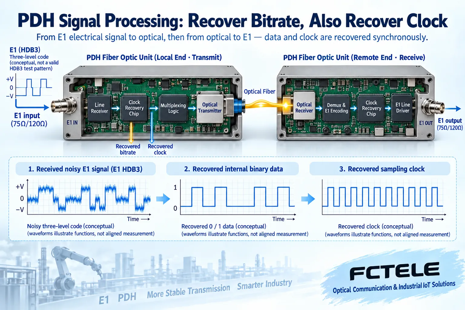
The voltage changes on the line and the internal binary data are not exactly the same thing. For example, the E1 line code listed in the Feichang Technology FCP-E4m details is HDB3, which can be understood as a level-code rule that meets line transmission requirements. The line receiver restores it into internally processable data, and the device then organizes the optical-side signal according to its own transmission structure. From this, one cannot infer that all PDH fiber transmission units use the same coding on the optical side, and one certainly cannot assume that two devices labeled E1 must be able to interoperate at the optical port.
2. Why clock recovery is also needed when recovering data
Digital reception does not mean that seeing a voltage immediately identifies a bit. The receiver needs to determine when to read the signal, and this moment is determined by the clock. The edges of the input signal may be affected by noise and transmission conditions; the clock recovery circuit extracts a suitable rhythm from changes in the received signal so that subsequent processing can continue continuously. Recovery here works within the input conditions allowed by the device; it does not repair any arbitrarily damaged signal.
You can think of bits as beads delivered one after another, and the clock as the rhythm when stringing beads. If the beads are there but the rhythm is wrong, you may miscount or miss them; if the rhythm is there but the beads are damaged, you also cannot get a correct result. This analogy only explains the relationship between data and time; it does not represent any specific circuit. In actual engineering, jitter, wander, and interface allowance conditions still need to be checked; jitter is a faster change in timing, and wander is a slower change. The specific judgment depends on standards and instrument results.
3. Why multiplexing must preserve channel identity
A multi-channel device needs to place each input into a distinguishable transmission organization, and the far end then separates the corresponding services according to the same rules. “Mixed transmission” does not mean randomly splicing all data together. Suppose three E1 ports are connected to dispatching, leased line, and test services respectively. The receiving end must know which channel the data comes from; otherwise, even if the number of received bits is correct, the service destination may still be wrong.
The plesiochronous digital hierarchy allows small differences in tributary clocks. Traditional PDH multiplexing structures accommodate such differences through corresponding adjustment mechanisms, and ITU-T G.742 gives the multiplexing requirements for positive justification at a specific level. This standard example cannot be directly treated as the internal frame format of a particular small-capacity fiber transmission unit. Modern products may use their own optical-side organization. Whether transmission is transparent, how channels are allocated, and whether clock settings are needed should all be based on the model manual.
4. Why effective service capacity is smaller than some “line rate” numbers
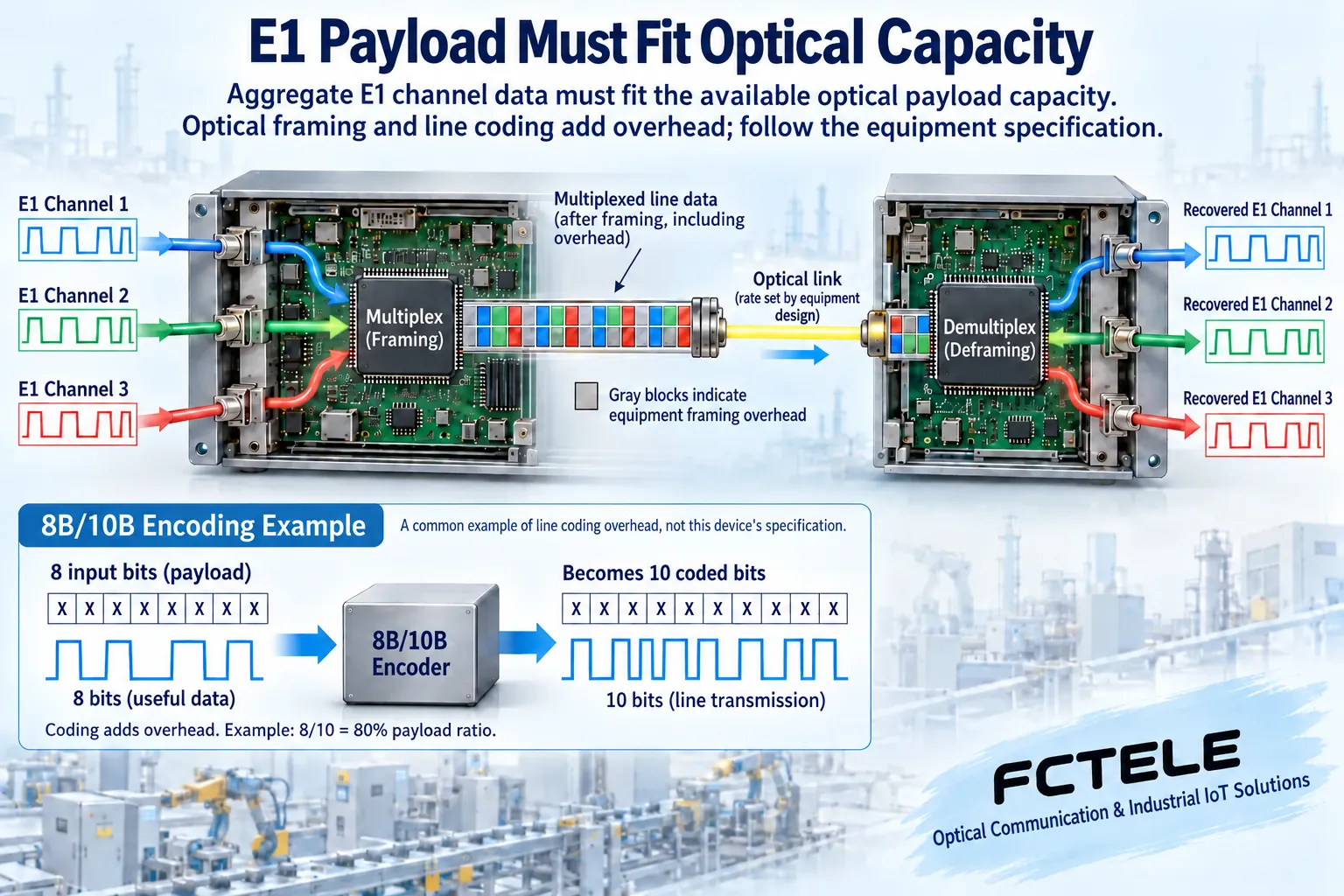
In addition to service data, the line may also contain frame alignment, channel identification, control, or coding overhead. The payload is the part that truly carries services beyond these extra organizational elements. Line rate, the number of E1 channels that can be provided, and Ethernet port rate are different indicators. You cannot pick out the largest number and treat it as the bandwidth every port can obtain.
A common misunderstanding is that “using 8B/10B allows more data to be transmitted without increasing bandwidth.” The name 8B/10B means that eight data bits are encoded into ten line bits. It introduces overhead and cannot be used as a reason for arbitrary capacity expansion. Coding has its own engineering purpose, but whether a certain coding exists, why it is chosen, and its specific efficiency are all determined by the device design. Ordinary users usually cannot freely change the optical-side coding in a menu, because the receiving methods at both ends must be consistent.
5. Optical amplification, error correction, and wavelength division multiplexing are not mandatory upgrade buttons
The optical transmitter maps electrical signals to optical signals, and the optical detector receives them at the far end. Many point-to-point devices operate directly according to the selected optical module and link budget, without needing an erbium-doped fiber amplifier placed along the route. Whether amplification can be introduced, and what wavelength and power range are suitable, is a complete optical system design issue. You cannot insert an amplifier on your own just because the distance looks long.
Forward error correction uses extra redundancy to help handle certain errors; wavelength division multiplexing lets different optical wavelengths carry different channels. Both require equipment and system support, and they are not functions that any PDH machine naturally has. The pairing of dual-fiber and single-fiber cannot be judged only by connectors. Different wavelength schemes, optical-side rates, and received power ranges must be checked. Production links cannot be optimized through unauthorized hardware trial matching.
6. The real optimization is to check the conditions at every layer clearly
First record the channels in use, port correspondence, interface impedance, and clock settings, and confirm that an idle channel is not being treated as a fault. Then check the power supply, fiber end faces, and receiving conditions, and finally observe per-channel bit errors and actual services. When a service is intermittently abnormal, distinguish optical link errors, E1 interface errors, and timing problems, rather than ruling out the transmission device just because the optical port is lit.
Taking Feichang Technology FCP-E4m as an example, the official website clearly lists one to four E1 channels, digital clock recovery, and remote loopback maintenance functions. Loopback sends the test signal back to help locate the link section; it does not increase channel capacity, and it is not equal to final service acceptance. If FCP-E4F1m is selected, its Ethernet port is an interface capability provided separately, and an ordinary E1 port cannot be directly treated as a network port. Product capabilities should be confirmed according to the purchased version, and the functions of one model should not be generalized to all PDH devices.
Suppose three E1 services show bit errors only on the second channel. First, during a maintenance window, check the wiring, clock, and test results at both ends of the second channel, then compare with the other channels. If all three channels are abnormal at the same time, focus on the shared power supply and optical transmission section. After testing, remove the loopback and restore services, and save the conditions, time, and results. Whether optimization is effective should be proven by tests under the same conditions, not by replacing more components as the basis.
Reference verification:ITU-T G.703 interface requirements, ITU-T G.742 multiplexing and adjustment, ITU-T G.823 timing requirements, Feichang Technology FCP-E4m. The illustrations are general principle diagrams, not actual product photos or measurement results. For specific operations, follow the model manual and carry them out during an authorized maintenance window.
Translated from the Chinese technical article. Source first published: 2024-04-22. Source last revised: 2026-10-13T12:21:24+08:00. Read the Chinese source
