


Accepting an SDI optical transceiver is not just about connecting the equipment and seeing a picture. A repeatable acceptance test should clearly define what format the source outputs, whether errors occur after transmission through the entire link, whether the optical reception is within the allowed range, and whether continuous operation is stable. Test items should correspond to actual needs and available instruments, and should not treat illustrative waveforms, manufacturer-promised distances, or a single indicator light as on-site measured conclusions.
1. First, write the test object completely
Record the specific models, hardware versions, power supply specifications, optical module configurations, and terminal models of the sending end and receiving end. Video mode should include resolution, frame rate, progressive or interlaced, SDI rate, and the mapping method involved by the equipment. Writing only 1080 or HD is not complete; passing a test at 1080p25 cannot prove that 1080p60 will necessarily pass; different modes should be verified separately for the items promised as supported in the requirements table.
At the same time, record the coaxial cable type and length, connectors and number of intermediate adapters, as well as the fiber type, end face, wavelength, connection, and splicing conditions. Requirements with embedded audio should specify the channels and actual format; when there are other services, the directions should also be checked separately. Do not add “supports all audio” or “automatically recognizes all standards” for functions that do not exist in the test. The object of acceptance is the purchased configuration, not a general equipment category.
2. Why the desktop baseline is important
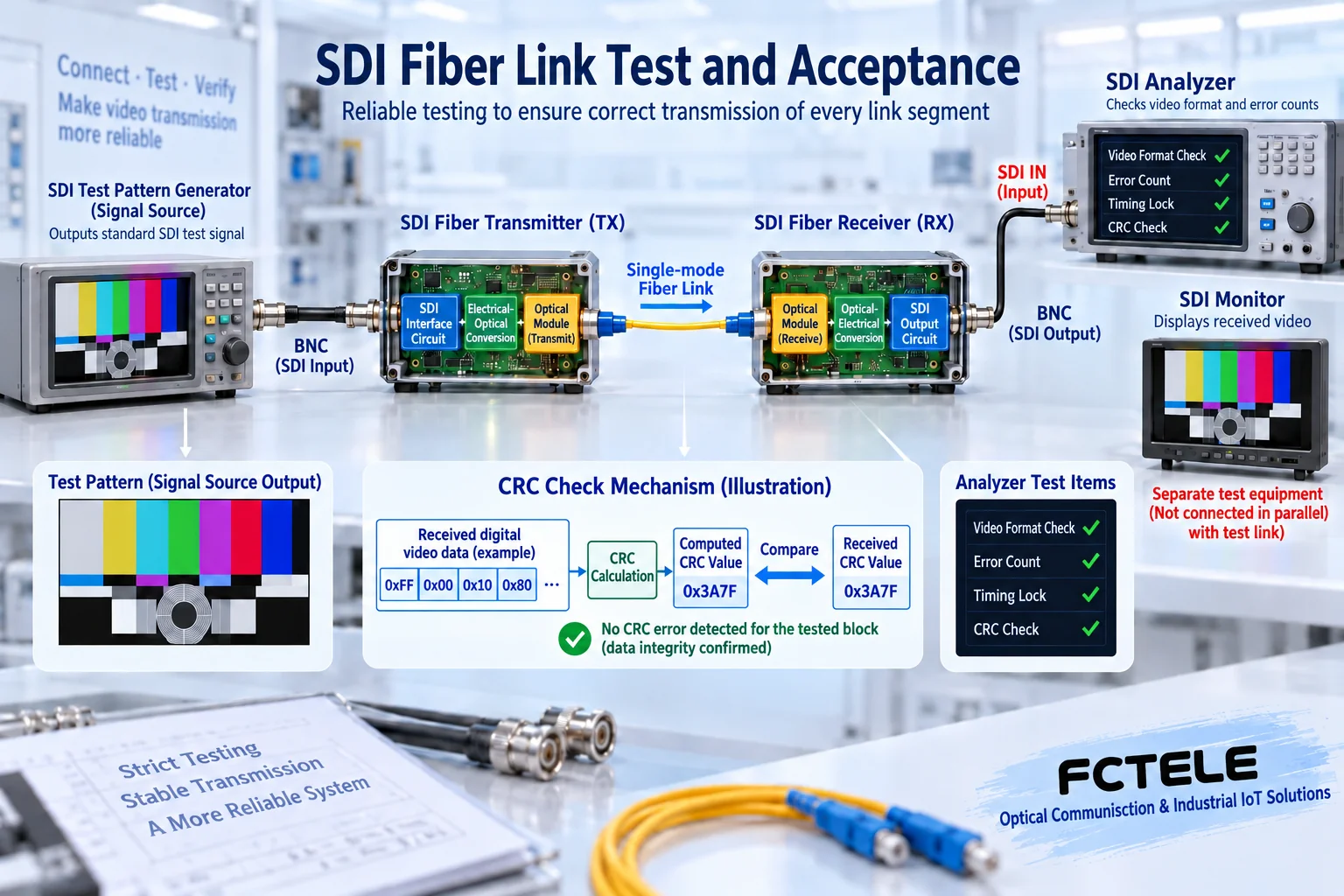
First use a qualified short coaxial cable, a known-good video source, and a terminal to connect the paired equipment under controllable conditions. Confirm that the source directly connected to the terminal is normal, then establish a baseline through the optical transceiver. Record the instrument-recognized format, picture and sound, and the equipment’s indicator status. This process helps eliminate initial format incompatibility; otherwise, if the entire system is moved to the site and a black screen occurs, it is difficult to determine whether it is an equipment or installation problem.
Test patterns should cover the required picture performance and be combined with moving pictures, actual audio, and daily switching operations. A fixed static picture can reveal some abnormalities, but it is not enough to verify all actual usage conditions. The test source and receiving instrument must also support the target rate; using an analyzer that only supports HD to test a 12G link, a no-signal condition cannot directly determine that the optical transceiver is unqualified.
3. Bit errors and CRC are not the same metric
Bit error rate requires knowing the data sent and the received result, and appropriate test equipment is needed to calculate it according to the corresponding method. An SDI analyzer may provide CRC errors of video data, format detection, and loss-of-lock events, all of which are valuable, but the number of CRC errors is not directly equal to the total number of bit errors, nor can it be arbitrarily converted into a precise bit error rate. The report should clearly state the metrics actually supported by the instrument and the measurement method.
Similarly, “no errors recorded during operation” is only an observation result under a given duration, mode, and instrument condition, not an absolute zero-error proof for unlimited time. When eye diagram or jitter measurement is required, use professional instruments, probes, and test methods that meet the rate and measurement point requirements. A common oscilloscope capturing a curve similar to a square wave cannot automatically prove that the SDI output meets the corresponding standard.
4. Measure optical power and check both upper and lower limits
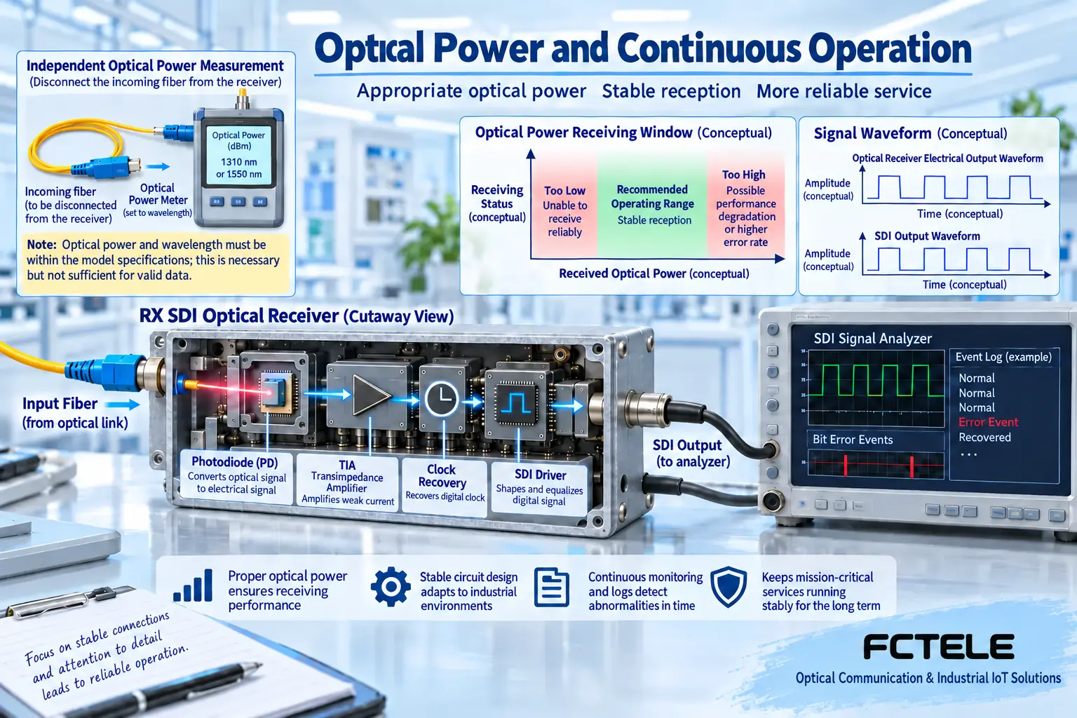
Use a power meter matched to the optical path wavelength and the correct interface for measurement, and record the reference conditions and measurement points. The received power should be compared with the sensitivity and overload point of that ordered configuration, and engineering-required margin should also be reserved. Writing only “optical power is very strong” is meaningless; too weak may cause loss of lock, and too strong may also cause overload. Instrument readings and connection losses should be handled according to the instructions, and do not look directly at the interface to check for light output.
The optical path budget can allocate the difference between the power available at the sending end and the receiving requirement to fiber length, connections, splices, and margin. It does not include the electrical loss of the input coaxial cable; the two sections should be checked separately. The distances for different rates and fiber configurations of Feichang Technology should be verified against the corresponding version. The maximum distance on the page cannot replace on-site power and service testing; when necessary, verify the boundary under suitable test conditions rather than changing laser parameters.
5. How to check continuous operation and fault recovery
Agree on the test duration according to project requirements, and record the start and end times, ambient temperature, power supply conditions, error counts, and abnormal times. Let the test cover the actual highest-demand mode and normal switching operations at the site. When measuring the temperature rise of equipment running under load, the measurement point and environmental conditions should be fixed; the temperature value needs to be compared with the equipment’s allowed operating range and engineering regulations, and the industrial temperature range of another series cannot be applied.
Fiber break, power failure, or source switching can be performed according to an authorized acceptance plan, and how the picture and audio recover should be recorded. Recovery time must be supported by actual measurement or model data, and a uniform millisecond number cannot be fabricated. For services that are broadcasting or recording, first arrange a test window and backup to avoid interrupting the link in use just to verify recovery. After testing, confirm that the equipment and wiring have returned to normal state.
6. Deliver a record that others can reproduce
The report should separate requirements, configuration, method, and results: the requirements list states which formats must pass, the configuration table states equipment and cables, the method states instruments and duration, and the results state actual readings and observations. Items such as eye diagram, bit error rate, or jitter for which instruments are not available should be clearly marked as not tested; ordinary monitoring cannot be used as a substitute for professional measurement to claim that all standards have been passed.
When abnormalities occur, keep logs, formats, indicator status, and segment-by-segment replacement results, then check the input coaxial cable, optical path, output coaxial cable, and terminal compatibility. If replacing with a short cable is normal, it does not mean that all functions of the optical transceiver are qualified, but it indicates that the next step should focus on the original link segment. A clear acceptance record can reduce repeated equipment replacement and also provide a reliable comparison baseline for subsequent expansion or rate upgrades.
At the same time, check all channel numbers and audio-video correspondence. For multi-channel equipment, apply load according to the agreed number of channels before observing. A single-channel test can only prove that single-channel condition and cannot replace a full-configuration test. Save the settings of the source and receiving instruments before and after the test to avoid using a different mapping or frame rate in the next round while still directly comparing with old results.
Sources:SMPTE Standards Index;Feichang Technology one-channel 3G SDI optical transceiver;Feichang Technology one-channel 12G SDI optical transceiver. The illustrations explain general mechanisms; they are not product physical objects, actual measured waveforms, or certification documents.
Related topics:How SDI optical transceivers work: coaxial reception, clock processing, and optical-electrical conversion;How to understand SDI synchronization: differences between bit clock, line/frame markers, and studio synchronization;SDI optical transceiver signal processing: what equalization, clock recovery, and retiming each solve;How to evaluate SDI optical transceiver power consumption and temperature rise: power loss, heat dissipation, and operation arrangements;SDI optical transceiver installation and troubleshooting: short-cable baseline, optical-link commissioning, and segment-by-segment localization;How to choose between SDI monitoring and IP monitoring: transmission, recording, latency, and security boundaries;How to troubleshoot no picture or no sound when converting SDI to HDMI: power supply, locking, and display compatibility
Translated from the Chinese technical article. Source first published: 2024-04-23. Source last revised: 2026-10-13T12:21:24+08:00. Read the Chinese source
