


VGA optical transceiver installation should first build a known-good short link before connecting field fiber. Otherwise, when the computer output, copper cable, transceiver, fiber, and monitor all change at once, it is hard to tell which section is causing a black screen. The debugging goal is not just getting a picture; it also means verifying text, color, aspect ratio, boot recovery, and stability for the actual application.
1. Before Power-On, First Understand the Direction of Both Ends
For common paired devices, the transmitter connects to the computer’s VGA output, and the receiver connects to the monitor’s VGA input; the input and output on the optical transceiver cannot be swapped based on plug shape. First check the model, order version, pairing relationship, fiber type, and connectors, then check the power supply voltage, polarity, and installation requirements. Power protection, chassis grounding, and cabling should be implemented according to the device instructions and on-site electrical codes. Do not temporarily borrow unknown adapters, and do not remove protective grounding just to try to eliminate interference.
2. First Save a Direct-Connection Baseline
Use a known-good short VGA cable to connect the signal source directly to the monitor, choose a fixed mode accepted by both sides, and photograph the display settings and test image. Fine text, vertical lines, color bars, and circles help check sharpness, sampling, color, and aspect ratio respectively. If the direct connection is already blurry or cropped, first troubleshoot the computer output and monitor settings; adding the optical transceiver to the link will not automatically eliminate source-end problems. Keep this baseline so that every later replacement can be compared.
3. How to Connect the Desktop Pairing Test
On the same workbench, connect the transmitter, a short fiber patch cord, and the receiver, still using short VGA cables on both sides, and keep the computer mode unchanged. Power on in the order specified in the manual, and observe the power, video, and optical path status lights, but do not apply the light names from other products. Only when the image and service pass can you say this combination works in that mode; all lights being on does not prove that color and timing are correct. Follow safe practices when checking optical ports, do not look directly into the interface, and use suitable tools to inspect and clean the end faces.
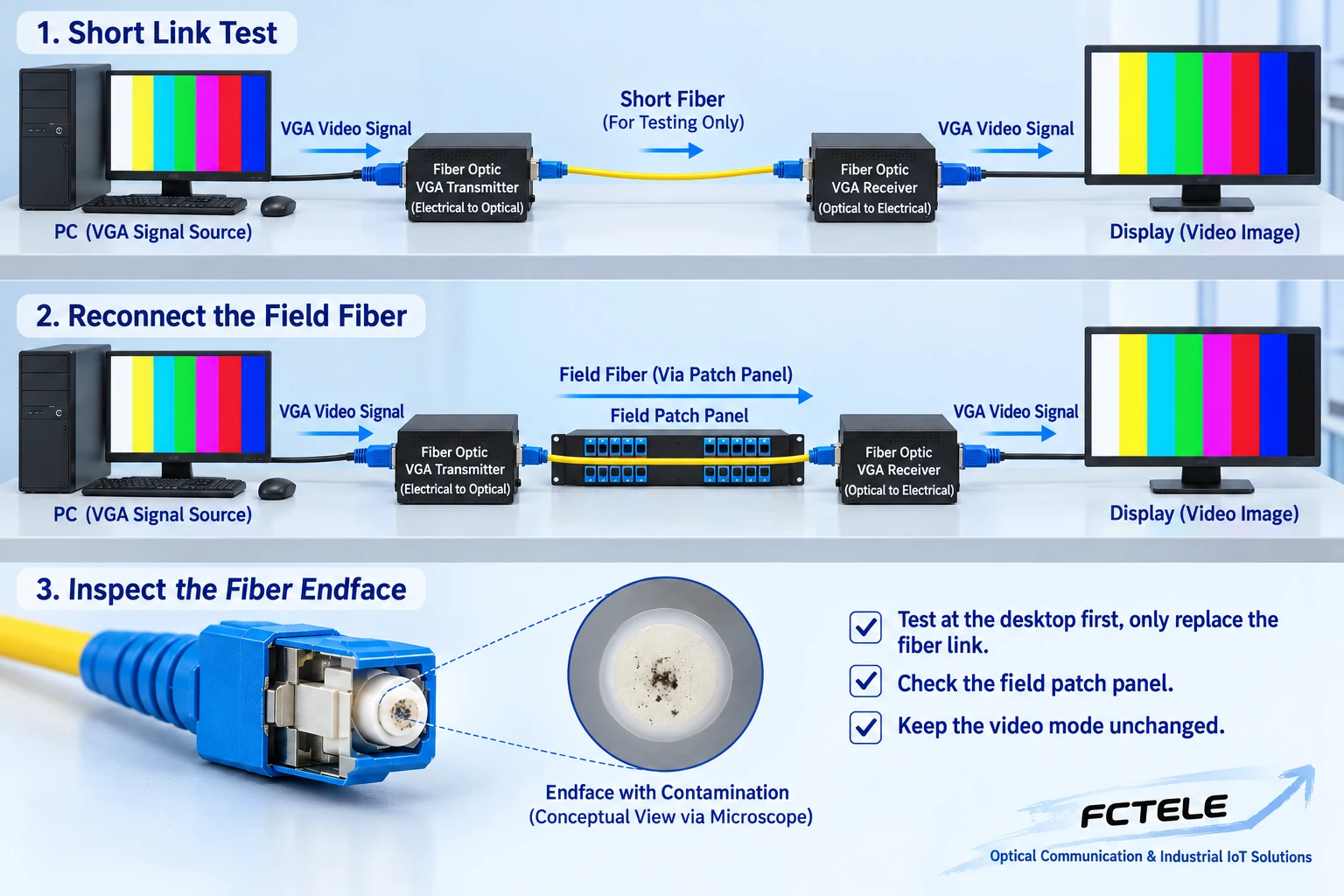
4. When Connecting Field Fiber, Change Only This Section
After the desktop test passes, replace the short patch cord with the actual line, and record the patch panel position, fiber core number, connectors, and splicing information. Check the allowed bend radius and pulling force, and avoid cabinet doors pinching the cable, connectors bearing stress, and contaminated end faces. For dual-fiber devices, check both directions according to the instructions; for single-fiber devices, connect according to the pairing requirements, and do not add a second fiber core based on experience. When necessary, measure the received power and link loss, and compare the results with the specific model range rather than only asking whether the light is on.
5. Where to Check a Completely Black Screen
First check whether the computer is still outputting the original mode and whether the receiver monitor has selected the correct input, then check the power and interface direction at both ends. Restore the monitor and short cable to a direct connection. If the direct connection works but the desktop pairing does not, the problem is in device configuration or compatibility range; if the desktop works but the field does not, focus on the field optical path and the environment at both ends. Replace only one known-good part at a time and record the result, to avoid a situation where two cables and one power supply are changed at the same time and the fault cannot be reproduced.
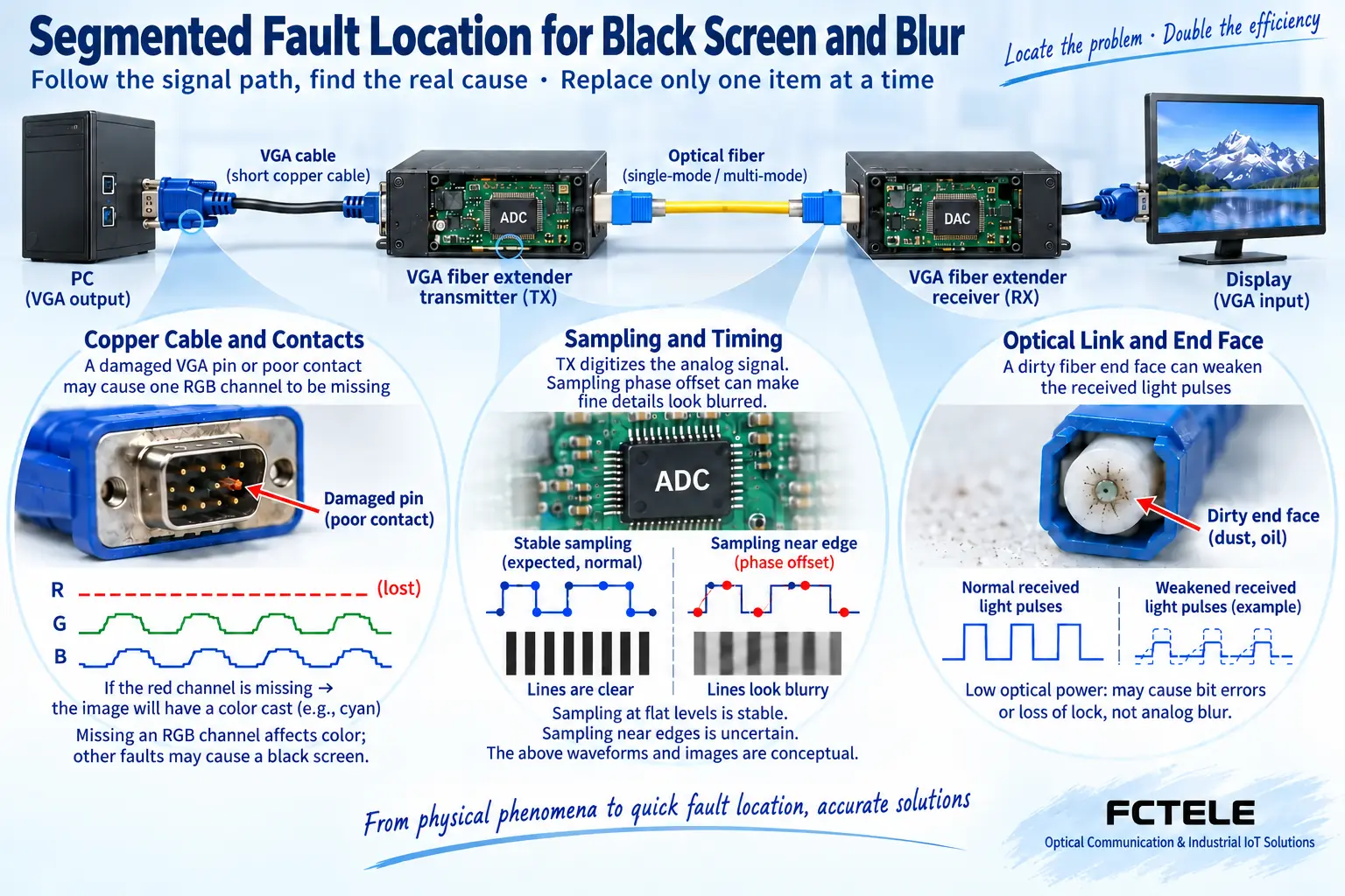
6. Missing Color, Blur, and Jitter Are Not the Same Fault
When red, green, or blue is missing, first check the analog copper cable and contacts; looseness or damage may affect one color path. When fine text looks faint, compare the direct-connection image quality, then check the input timing, sampling adjustment, and the monitor’s auto-adjust function; if the device does not expose a certain setting, do not look for a nonexistent knob based on an article. If the image is shifted left or right or the edges are cropped, check the timing and display aspect ratio. Occasional jitter should be recorded with the conditions under which it appears, distinguishing continuous blur from momentary loss of lock, and it should not all be attributed to fiber length.
7. Source Switching and Reboot Must Be Verified Separately
Display identification information processing, signal source output strategy, and receiver startup state may affect the mode after power is restored. Test computer-first startup, monitor-first startup, link recovery, and signal source switching within the authorized range, and observe whether manual operation is needed. If the fault appears only after switching, record the modes and power-on order before and after, rather than directly concluding that the optical receiver is damaged. Back up the settings of configurable devices before changes, to avoid breaking a mode that has already passed just to eliminate one symptom.
8. Acceptance Should Look at Actual Content
Suppose an old industrial control interface has small fonts, alarm colors, and pop-up windows; use the actual software to verify it, and also add a test pattern to check boundaries and aspect ratio. Moving content can help find abnormal frame updates, while long-term observation records intermittent black screens and their time points. During testing, do not intentionally create dangerous electrical interference, and do not hot-plug parts that the manual prohibits hot-plugging. Agree on the observation time, pass conditions, and recovery actions, save fault screenshots and link logs, and let maintenance personnel recheck by the same method during handover.
9. How to Keep Maintenance Records
Record the models and versions at both ends, power supply information, source mode, monitor model, VGA cable length, optical path measurement results, and the conclusion of each replacement. The Feichang Technology VGA category can be used to find product entry points. Whether a specific model has equalization, compensation, and corresponding status lights should be confirmed according to the corresponding version documentation, and the same settings should not be applied to all devices. Formal installation should obtain the corresponding version of the manual. For basic principles and purchasing checklists, refer to the other two articles in this group, but during troubleshooting, on-site evidence should still be the basis.
During maintenance, if the image is normal only when the cabinet door is open, first record changes in power, temperature, and cable stress, and have qualified personnel inspect it; do not immediately attribute it to some kind of insufficient shielding. If switching back to the short patch cord restores operation but the field fiber still does not work, keep the measurement results for both connections and continue checking connectors, fiber cores, and the budget. When replacing the receiver, the paired model must be reconfirmed; spare parts that look the same may have different optical port configurations. Fixing the passing baseline can reduce repeated trial and error and unsupported repairs.
Sources:Analog Devices: RGB graphics sampling and synchronization clock materials;Analog Devices: analog graphics and HDMI interface processing materials;Feichang Technology: VGA optical transceiver category entry. The illustrations explain general mechanisms; they are not product photos, measured waveforms, or certification documents.
Related topics:VGA optical transceiver working principle;VGA selection checklist;Classroom and meeting room planning;Difference between SDI and VGA;HDMI and VGA interfaces;VGA to HDMI and image quality;Special equipment room solutions
Translated from the Chinese technical article. Source first published: 2024-04-19. Source last revised: 2026-10-13T12:21:24+08:00. Read the Chinese source
