


First, the task: send existing leased line services to another location
Between a campus control room and a remote site, several E1 leased lines may be retained. The equipment at both ends needs to continuously receive the original digital services, but the middle must cross a longer distance or connect to an already-built transmission network. In such scenarios, an SDH optical multiplexer handles service access, transmission organization, and remote recovery; it will not automatically understand telephone dialing, industrial commands, or all video formats just because a fiber is connected.
SDH is short for Synchronous Digital Hierarchy, which explains how digital services enter a specified transmission structure. E1 describes a digital line interface, and Ethernet describes another set of network services; these names and bearer systems are at different layers. First determine what the equipment at both ends outputs, how many channels to retain, and in which direction, then choose the transmission method. This avoids replacing a complete solution with an interface count table.
How E1 enters SDH: adaptation, mapping, and add/drop
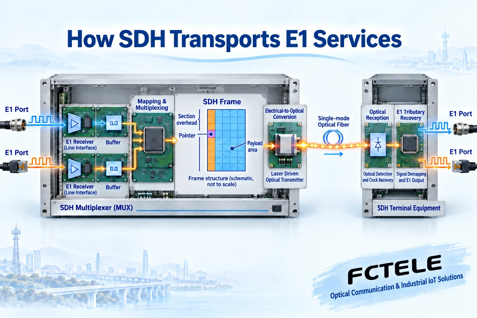
Taking a common E1 tributary as an example, the ingress circuit first receives the specified line signal, handles line coding, clocking, and necessary interface conditions, then organizes the digital information to be carried according to mapping rules. Mapping can be understood as arranging services into positions that the far end can recognize, but it does not assign an IP address to them. When wiring, you still need to confirm impedance, framing mode, line coding, and transmit/receive relationships.
A virtual container is a digital structure that carries services and corresponding path overhead, often written as VC in English. Path overhead supports functions such as transmission monitoring; a virtual container is not a physical container inside the chassis. Common E1 low-order mapping involves structures such as VC-12, which then enter higher-order bearers through corresponding combinations. The complete process has multiple layers, and a single blue block in a simplified diagram cannot be treated as all frame bytes of a certain model.
Some nodes need to drop part of the service for local use while the rest continues to the next site; this is an entry point for understanding add/drop multiplexing. How many channels a node can drop and where cross-connections go are limited by boards, mapping, and configuration. It works differently from a switch forwarding frames by MAC address, and you cannot assume arbitrary ring networking capability just because there are two optical ports.
Synchronous frames, pointers, and rates: line capacity is not equal to port count
A typical STM-1 frame consists of nine rows and 270 columns of bytes, with a frame period of 125 microseconds, corresponding to a line bit rate of 155.520 Mbit/s. This value includes transmission overhead and cannot all be treated as customer net service bandwidth. The grid in the figure only explains the relationship between overhead, pointers, and payload; it is not drawn according to actual column count, byte proportions, or product internal wiring.
Pointers help locate the starting position of the corresponding bearer structure and support specified timing adaptation. A pointer does not indicate which IP destination the optical signal goes to, nor does it mean user data can be arbitrarily deleted. SDH lines use an organized synchronous structure, and the carried tributaries may still have their own clock conditions, requiring correct mapping and recovery. “Synchronous” cannot be understood as all on-site interfaces being forced to use the same clock.
Under classic mapping conditions, one STM-1 bearer structure can arrange a corresponding number of low-order services, but whether a specific device has the required E1 boards installed, whether all channels are enabled, and which service mapping is used must be confirmed separately. A device with only a few E1 ports on the panel will not magically gain dozens of connectable interfaces just because the optical line rate is higher.
Why protection can recover: first there must be another available path
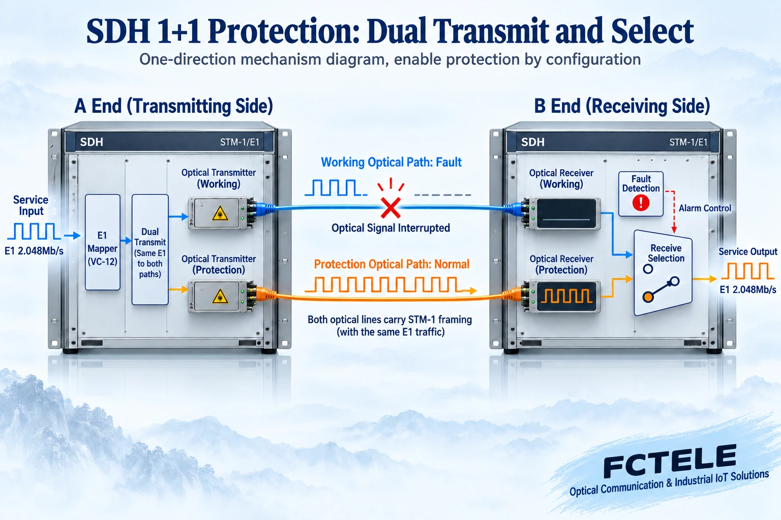
In a simplified unidirectional example of linear 1+1 protection, the transmitter sends the same bearer information simultaneously to the working and protection paths, and the receiver selects a qualified input based on defect detection and configuration. When the working path fails but the protection path is still available, the receive selection can switch to the latter. In the figure, two optical receivers enter a selection circuit and only recover one copy of the customer service; they do not superimpose and output two copies of data.
Ring protection has different organization methods, and the simplified linear 1+1 diagram cannot be directly treated as the complete mechanism of all SDH rings. You need to check the protection layer, working and protection resources, switching conditions, priorities, and recovery strategies. If two fibers share critical elements on the same fragile cable, the same power supply, or the same faulty device, they may still fail together.
Protection switching requires corresponding equipment capabilities and correct configuration, and may also cause brief service impact. You cannot infer from the word “self-healing” that any dual-point failure can be recovered, or promise zero interruption in any scenario. Formal projects should agree on test conditions according to service requirements and verify a single failure, the recovery process, and alarms within a maintenance window, rather than only observing how many lights are on the chassis.
Fiber and clock are two sets of conditions that both must be checked
The transmit-side circuit drives the optical transmitter so that the optical signal carries digital information; the far-end photodetector and recovery circuit then restore the corresponding digital stream, and the service is extracted according to the mapping relationship. Fiber carries information; the original current does not pass through the glass to the other end. Optical power, rate, and frame structure describe different conditions: having received light does not mean frames can be recognized; normal frames do not mean every tributary is wired correctly.
For the optical path, check fiber type, wavelength, interface, transmit range, receive sensitivity, overload upper limit, and path loss. You cannot judge a link only by nominal kilometers, nor should you unconditionally directly connect a long-distance optical port to a very short patch cord. For clocking, preserve the source, priority, behavior after loss of reference, and recovery settings to avoid nodes forming unreasonable synchronization relationships.
Which advantages and limitations affect engineering choices
For continuously running leased lines, clear service mapping, monitorable transmission paths, and supporting protection make it easier to write communication relationships into a verifiable channel table. When a node needs to maintain a particular service, you can find the ingress, bearer position, and egress based on configuration. This value comes from complete equipment and network design, not from automatically gaining all management functions just by “using fiber.”
On the other hand, pre-allocated circuit resources may not be shareable to all burst traffic like a packet network when services are idle. Boards, chassis, power consumption, spare parts, and maintenance staff skills also constitute costs. Leased line transport does not automatically provide encryption, access control, or application-layer security; systems involving protection and scheduling still need the corresponding service systems to meet their own requirements, and one transmission device cannot replace the entire security design.
How existing systems evolve: plan by interface and lifespan
Maintaining an existing SDH network and building a completely new packet network are different engineering tasks. The former should first inventory the E1 services, mapping, clocking, protection, and spare parts that still need to be retained, then evaluate expansion or replacement. You cannot infer from the market description in an old article that all industries today use the same technology, nor should you decide to decommission a critical leased line based only on equipment age.
If planning to switch to packet transport, verify how services are encapsulated, how the far end recovers clocking, and whether latency, jitter, packet loss, and the recovery process meet the original system. A high nominal Ethernet port rate does not prove it can directly replace any E1 circuit. During the transition, retain the original configuration and service test baseline, migrate circuit by circuit according to plan, and then check common failure points and fallback conditions.
When checking Feichang Technology products, distinguish categories and delivered models
The Feichang Technology product center lists SDH optical multiplexers separately from ordinary PDH and E1 interface devices, so when searching you can first locate by existing network and service ingress. Category names help narrow the range but cannot replace the line interface, mapping, board, and protection descriptions of a specific model. Without verifiable specifications, do not infer STM level, total port count, or fixed recovery time from the category name.
Quotation materials should include equipment at both ends, number of service channels, existing transmission network interfaces, rack space, fiber conditions, and maintenance method. For interconnection with an existing network, also state the peer equipment and interoperability conditions to be verified. Clearly writing the optional boards, optional power supplies, and actual delivery combination can prevent multiple capabilities in a brochure from being mistaken as standard on every device.
Turn a requirement into an acceptable project
Assume three E1 services need to be maintained between two buildings: first measure that each original short link is normal, then record wiring, impedance, framing, and clock relationships. If it is only a point-to-point extension, compare matching point-to-point devices; if access to an existing SDH node, along-route add/drop, or agreed protection is required, continue checking the corresponding bearer structure and node capabilities. This is a hypothetical example, not a completed customer case.
During commissioning, verify one channel first, then check all channel mappings; then run the planned services simultaneously and observe bit errors, alarms, and actual system performance. Protection tests are conducted according to an approved maintenance plan, recording the disconnected path, affected services, recovery process, and post-recovery configuration. Finally deliver port correspondence, optical budget, clock source, and test records so maintenance staff can explain where a service anomaly occurs.
Documentation note: The principle diagrams have been checked for technical content and are used to explain general mechanisms; they are not product photos or measured records. Specific interfaces, modes, and capabilities are subject to the selected model, version, and on-site verification.
Verification references:ITU-T G.703 digital interfaces
ITU-T G.707 Synchronous Digital Hierarchy node interfaces
ITU-T G.783 equipment functional blocks
ITU-T G.841 protection architecture
Feichang Technology SDH product categories
Related technical topics:How to choose between PDH and SDH optical multiplexers: clock adaptation, service mapping, and interoperability conditionsHow to check PDH/SDH optical multiplexer alarms: LOS, LOF, AIS, RDI, and bit error location
Translated from the Chinese technical article. Source first published: 2020-04-29. Source last revised: 2026-10-13T11:40:22+08:00. Read the Chinese source
