


PDH fiber transmission units are often used to send digital services such as E1, which the equipment supports, over fiber to the other end. They can suit clear point-to-point leased line needs, but you cannot treat all of SDH’s synchronous frames, network protection, or management capabilities as natural advantages of PDH. Whether a PDH fiber transmission unit fits a project should be judged from the service interfaces, number of channels, clock relationship, and maintenance requirements.
First separate the service equipment from the transmission equipment
Service equipment generates or uses data, while transmission equipment sends compatible signals to the far end. For example, one device outputs E1, another device at the far end receives the corresponding E1, and in between you can choose optical transmission equipment that supports that interface. An fiber transmission unit cannot directly receive any network port or translate all application protocols just because the word “digital” appears in its name.
Beginners can think of it as a dedicated transport tool between two ends. But a transport tool has loading rules: the service interface and rate, channel organization, and clock conditions all need to match. Fiber is only the transmission medium and cannot remove these rules. When purchasing, writing “what service is being carried” before “how far it must go” often helps you find selection errors earlier.
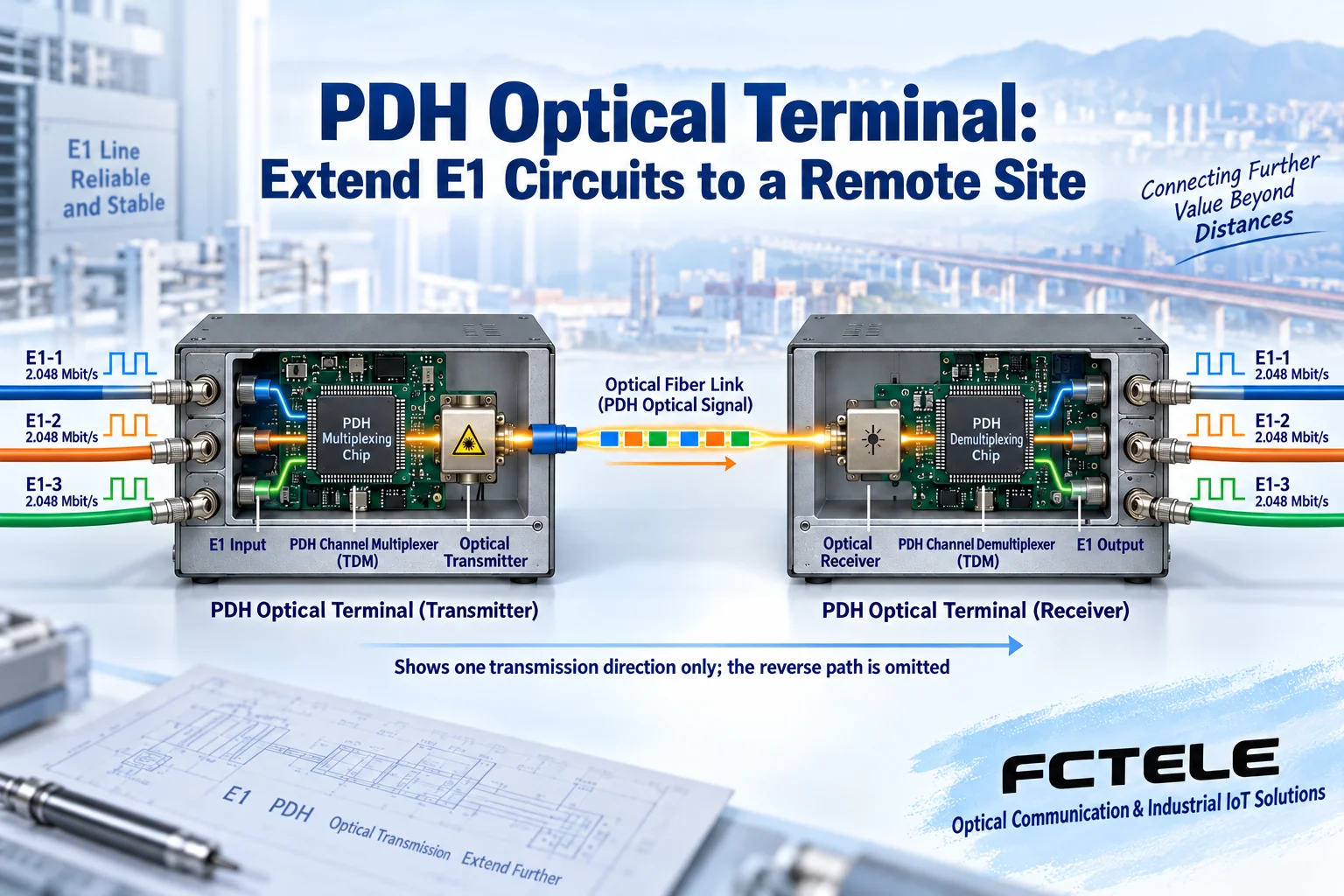
How one channel and multiple E1 channels pass through fiber
The sending end organizes the supported services into transmission data and then drives the optical transmitter; the receiving end recovers the data and forms the corresponding service interface output. Multi-channel equipment also needs to distinguish different channels clearly, and the far end splits them according to the agreed structure. The common nominal rate of E1 is 2.048 Mbit/s, and its electrical and frame structure requirements cannot be directly replaced with ordinary Ethernet rules.
If you use only three channels while the equipment supports four, you can, when configuration allows, clearly leave the unused channel empty and record it. That way, when maintenance staff see no service on the fourth channel, they will not mistake the expected empty state for an outage. How channel numbers correspond at both ends should be confirmed according to the manual and actual testing, not just by looking at wiring order.
Why PDH is called plesiochronous or approximately synchronous
Different digital signal sources each have their own clock, and their frequencies may be close but have tiny differences. The PDH hierarchy must handle these differences during multiplexing, so multiple inputs cannot be assumed to be absolutely synchronized. The corresponding adjustment mechanisms in traditional multiplexing structures exist to accommodate such rate differences under certain conditions.
Imagine several people passing digital signals at their own rhythms: at first their pace is close, but over time there may be differences in order. The equipment needs to handle timing, rather than randomly squeezing bits together. This metaphor does not explain which buffer, adjustment, or encapsulation a particular product uses; the specific implementation still depends on the manufacturer’s documentation. A product name cannot replace a frame structure description.
SDH is not just another name for PDH
SDH uses the frame structure and corresponding mechanisms of the synchronous digital hierarchy. It differs from traditional PDH in multiplexing, clock organization, and service processing methods. You cannot move SDH’s byte structure or management features into a PDH introduction and write them as advantages that all PDH fiber transmission units have. References such as ITU-T G.707 discuss the SDH hierarchy, and they cannot be confused merely because both use fiber.
“Using a synchronous structure” also does not mean all SDH systems are naturally fault-free. Protection switching, network management, and specific service functions require support from actual equipment and network solutions. When comparing, separate the technology hierarchy from the product implementation: the hierarchy explains principles, while product details state what a particular model provides, and the two cannot replace each other.
Why point-to-point transmission may make boundaries easier to define
In scenarios with fixed endpoints and a clear number of services, the path and channel correspondence of point-to-point equipment are easier to record. For example, if several clear E1 leased lines only need to be extended between two locations, you can design around channel capacity, optical interfaces, clocking, and power supply, and you do not necessarily need to expand the whole project into a complex transmission network.
But “easy to record” is not “no planning needed.” If you later need to add sites, aggregate across multiple areas, manage uniformly, or use protection topologies, you should check expansion methods in advance. You cannot directly combine a pair of point-to-point devices into any ring network and then claim it already has automatic protection capability. The clearer the scope of application, the more reliable the solution judgment.
Why the optical port can be lit but the service may still be incorrect
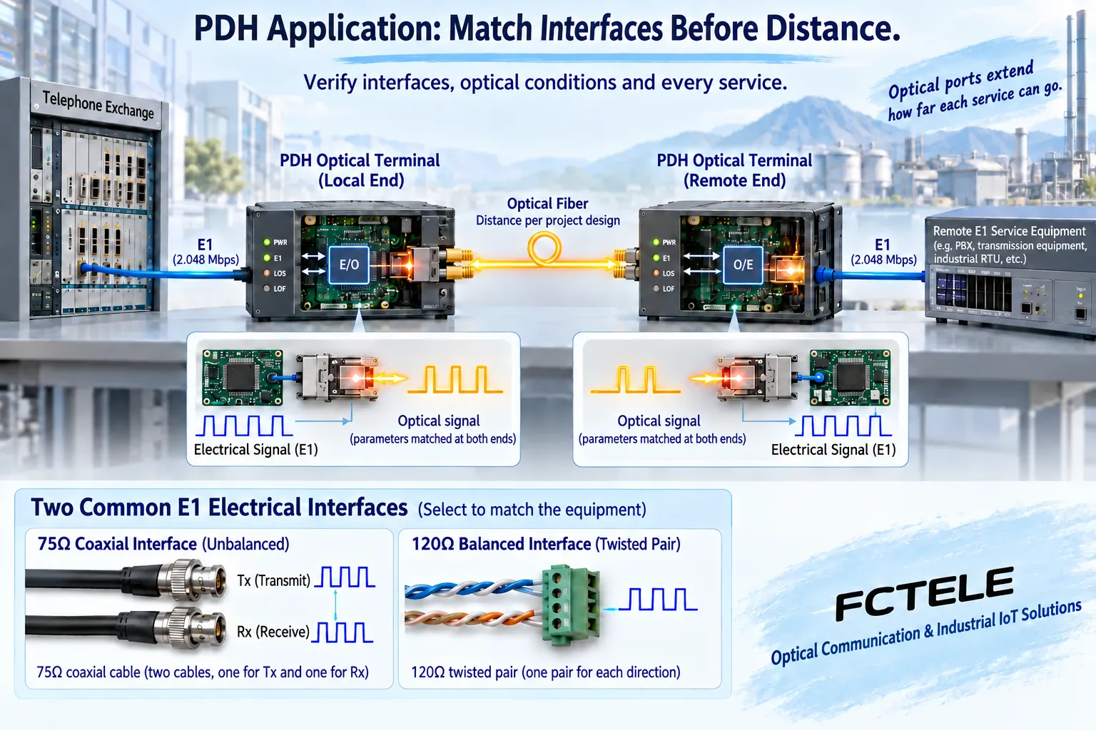
Link status can reflect some physical conditions, but it cannot prove that all channels correspond, the interface methods are correct, and the clocking is correct. After the receiving end gets the optical signal, it still needs to correctly recover the data and output the service. If the E1 methods at the input and output ends are inconsistent, or the received format is incompatible, the final service may still fail.
Another situation is that the link stays lit but bit errors or intermittent abnormalities occur. In this case, troubleshoot by combining optical reception conditions, error statistics, service interfaces, and clock relationships, rather than replacing the whole device just because a light is on. Optical power values need to be compared with the allowed range of the actual model; you cannot apply one fixed set of “normal values” to all products.
How the features of Feichang FCP-E4m can be used for selection
The official details of Feichang FCP-E4m provide related product configurations for 1 to 4 E1 channels and describe a status capability used to distinguish remote power loss from fiber breakage. This helps point-to-point maintenance: the first place to check differs for the two faults, which can narrow the troubleshooting scope. Additional functions such as service telephone and loopback should be confirmed according to the actual configuration, and optional items should not be promoted as standard capabilities of all equipment.
This product information can serve as a selection clue for small-capacity E1 leased lines, but it cannot prove that the entire PDH category has the same alarms, capacity, and functions. If Ethernet, management interfaces, or a different number of channels are needed, check the corresponding specific model; you cannot infer compatibility with all service equipment from the series name.
What conditions should be checked first when replacing equipment
You should save the original equipment model and version, service interface form, channels used, clock method, and optical interface parameters. Even if both old and new equipment are labeled PDH or E1, you still need to confirm that the combination at both ends can interoperate. The fact that a fiber connector can be inserted only shows part of the connector conditions; it does not show that the optical-side rate and transmission encapsulation are consistent.
The replacement plan should also include a maintenance window and a recovery plan. Do not directly try an unknown model on production services, and do not leave a test loopback in the link for a long time. Loopback helps locate a certain section, but it does not replace final end-to-end service acceptance. This article discusses judgment conditions; specific settings need to be checked in the equipment manual.
How to verify a project with three leased lines
Suppose there are three E1 services between two locations. First write down the source, destination, and port correspondence of each of the three services. After choosing equipment that supports the corresponding capacity, confirm the channels one by one and record unused ports. Then check power, fiber, interfaces, and clocking so that test results can correspond to each leased line, rather than only recording “optical port normal.”
After completion, observe bit errors, continuous operation, and power-off recovery performance according to project requirements. If the equipment provides a specific fault identification function, it can be verified under authorized test conditions, but you cannot derive recovery time or absolute losslessness on your own. Whether to choose PDH or another solution should ultimately be based on these verifiable requirements, not on slogans such as “new technology must be more advanced” or “old technology must be unsuitable.”
Verification materials:Feichang FCP-E4m;ITU-T G.704;ITU-T G.707 SDH hierarchy. The diagrams explain general mechanisms and are not wiring diagrams for a specific model.
Why ordinary telephones, cameras, and PLCs cannot be directly connected to any PDH
E1 can carry voice or data already organized by service equipment, but an E1 port is not the FXS port of an ordinary telephone. Analog telephones need corresponding voice interfaces and multiplexing stages; ordinary IP cameras usually output Ethernet services; PLCs may use Ethernet or serial interfaces. You cannot infer from “the industry uses it for power, transportation, or surveillance” that a pure E1 device can directly connect to these different signals. The correct question is what the field device actually outputs and whether the purchased model has the corresponding interface.
If the same optical link needs to carry both E1 and Ethernet, you can choose a product that clearly provides both types of interfaces and check the capacity. For example, the official details of Feichang FCP-E4F1m separately list one to four E1 channels and one 100 Mbit/s Ethernet port. This is the capability of a specific model, not a default network port on all PDH equipment. The E1 rate and the Ethernet negotiation rate cannot simply be added together and advertised as the service capacity available to each channel. During loopback testing, also distinguish E1 service loopback from Ethernet forwarding to prevent incorrect operations from affecting other services.
How to optimize traditional networks instead of blindly upgrading
Optimizing old leased lines starts with taking inventory of services and troubleshooting bottlenecks: how many channels are actually used, whether there are idle channels, which line has bit errors, and whether power supply is abnormal. Replacing faulty equipment and link sections with compatible versions and organizing port numbers and test records is often more helpful than pursuing a higher advertised optical-side rate. You cannot arbitrarily change the equipment multiplexing method to frequency division or code division, and you cannot claim that refreshing firmware will provide channels that did not originally exist.
Using backup power, backup paths, or network protection depends on what the specific model and complete solution support. Resistance to electromagnetic interference is mainly an advantage of fiber as a transmission medium; power, grounding, and copper-cable service ends still have corresponding risks. Encryption, ring self-healing, optical power monitoring, and remote management are not promises carried by the name PDH; whether they exist and how to verify them must be based on equipment documentation and the on-site solution.
Is PDH still suitable today
When there are already clear E1 services, only two sites need to be connected, both ends match, and maintenance resources are sufficient, a point-to-point PDH solution is still worth comparing. For new large-capacity packet networks, multi-site aggregation, or unified network management projects, you should compare SDH, packet transport, or other bearer solutions based on actual requirements, and you cannot apply the conclusion that “all projects are cheaper.” Costs also include spare parts, testing, maintenance windows, and future expansion, not just the equipment quote.
This article does not infer market share just because a product is still being sold, nor does it predict that the entire industry will continue to grow or exit immediately. What customers really need is whether existing services match, whether performance can be accepted, and whether maintenance can continue. To further understand signal processing, see PDH signal processing and efficiency boundaries; for E3/E4 or bearer system migration, see Service levels and legacy network migration boundaries, and do not use this introductory article on small-capacity E1 as a substitute for specialized judgment.
The principle diagrams are general illustrations, not product photos, teardowns, or measurement results. Supplementary verification:G.703 interface,Feichang FCP-E4F1m details.
Translated from the Chinese technical article. Source first published: 2020-01-18. Source last revised: 2026-10-13T13:13:08+08:00. Read the Chinese source
