


First write the alarm down completely, then decide which section to check
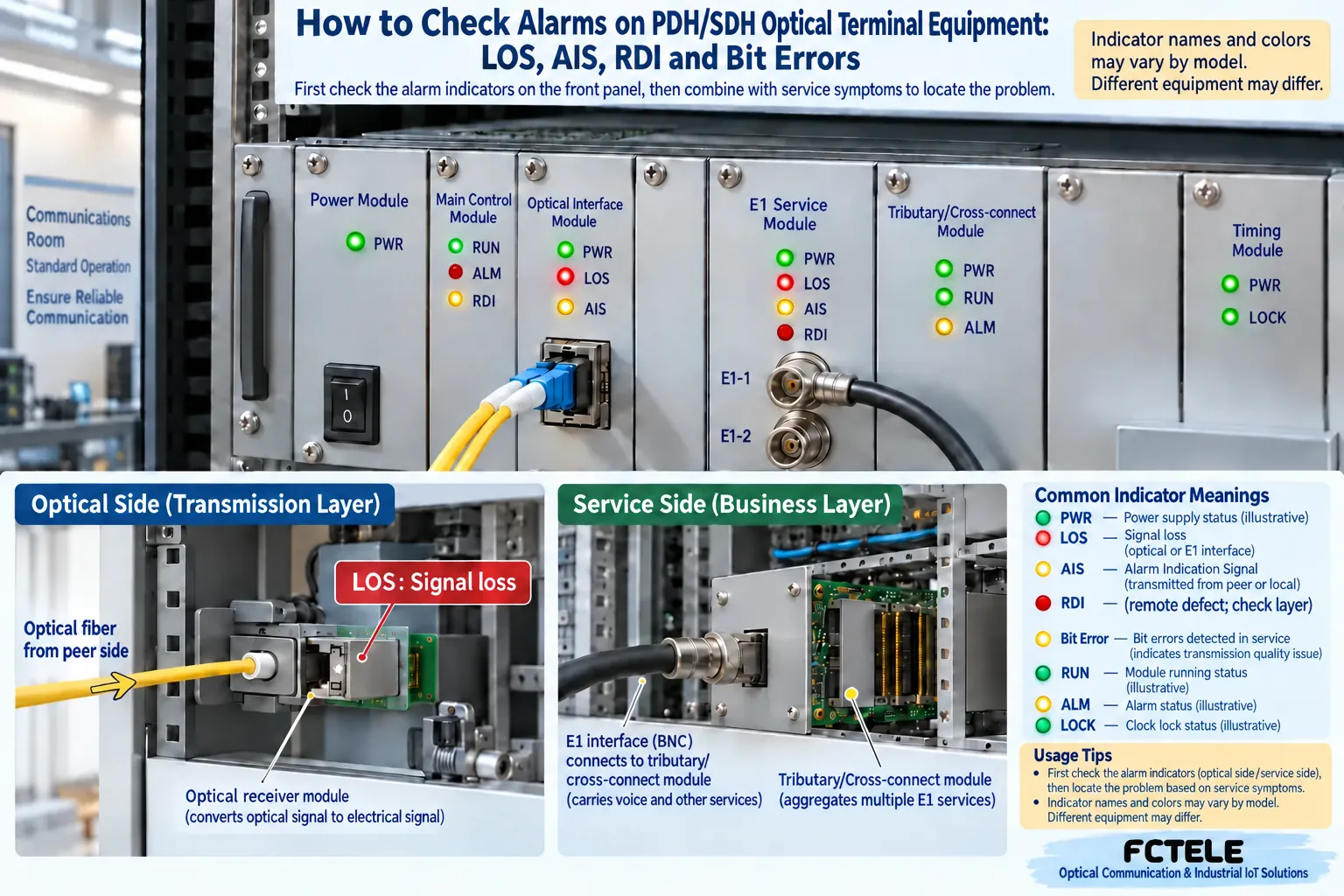
When a red light appears on the optical multiplexer panel, the first step is to record the light name, the board or port it is on, the time it occurred, and which services are affected. The line, tributary, synchronization and management alarms of PDH and SDH equipment may all be displayed together in the same chassis. A general alarm being on does not mean all E1 links are down at the same time, and it cannot directly prove that the optical cable is broken or that the whole unit is damaged.
Photograph the complete model numbers, versions, panel labels and wiring at both ends, and save the alarm objects and time records in the network management system. If only one service channel is abnormal, first clearly record that channel’s input, mapping and output; if multiple channels fail at the same time, then check the power supply, optical path and bearer structure they share. Keeping evidence first can avoid having only the sentence “it used to be disconnected” left after a restart.
Power status and management access are both limited clues
The PWR light usually helps observe power status, but the specific meaning of its color and whether it is on or off must be checked in this model’s manual. The light being on cannot by itself prove that all power parameters, internal boards and service processing are normal. When both ends show no response, first confirm the on-site power supply and equipment connections; work involving power measurement, grounding and internal equipment inspection should be carried out by qualified personnel according to maintenance procedures.
Being able to access the network management system means the management path is available under current conditions, and it does not replace an E1 service test. Conversely, if the network management address is unreachable, it may also be caused by management configuration or the network path, and you cannot immediately conclude that the bearer circuit has completely failed. Recording equipment operation, management reachability and customer service as three separate items can narrow down the fault scope.
LOS and LOF: check the signal and frame recognition separately
LOS usually means the corresponding receive interface cannot detect a signal that meets the conditions. First identify whether it belongs to the optical port or the E1 tributary: an optical-side problem may involve the far end being powered off, a broken line, contaminated end face, abnormal transmission or unsuitable received power; a tributary-side problem may be that the service end has no input. Do not use exactly the same wiring operation just because you see the same abbreviation.
LOF means the correct recognition of the corresponding frame cannot be maintained, and the receiving end may still be able to measure an optical or electrical signal. At this time, check the far-end rate, frame conditions, signal quality and other alarms. Normal optical power cannot prove that the frame content is correct; received power being too high can also cause problems, so you should not generally think that stronger light is always better. The interface range and necessary attenuation must be checked against the actual optical module specifications.
AIS and RDI: trace the fault impact along the service direction
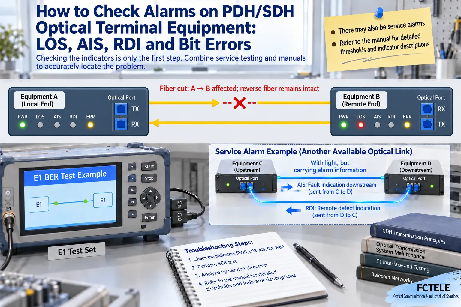
AIS is an alarm indication, and the equipment can notify downstream at the corresponding layer that the upstream service has been affected by a defect; RDI feeds the detected far-end defect back to the corresponding upstream. They are locating clues and need to be interpreted together with the multiplex section, path or tributary object. Similar names may appear at different layers, so you cannot treat every AIS as a local optical port disconnection, nor directly translate RDI as the far end’s whole unit being damaged.
The same root cause may trigger a series of subsequent indications. Organize the time records at both ends, first look for the earliest direct defect, then check how the subsequent AIS or far-end feedback propagates along the path. The broken fiber and alarm propagation in the figure are simplified explanations of different scenarios; when an optical signal is present, you may also receive only an alarm indication rather than valid customer service.
For example, if one E1 input at the far end is unplugged while the optical bearer at both ends is still normal, the local end may observe an abnormality or alarm indication corresponding to that service. You should return to the far-end tributary to check the source-end status and wiring, rather than repeatedly replacing the entire optical path. Whether a particular alarm is generated, how it is named and where it is displayed still depends on the equipment implementation and configuration.
When only one E1 channel is bad, check the tributary and mapping table
Write down the abnormal E1’s port number, connector, impedance, line coding, framing and transmit/receive direction item by item, confirm that the service source end is running, and that the channels at both ends really correspond. When multiple interfaces share an optical bearer, one channel having no input does not necessarily affect the other tributaries. The same port appearance does not mean its pins or configuration can be directly replaced.
Whether unused tributaries are enabled and how alarms are handled should be configured and recorded according to the equipment rules. Alarm masking only changes indication or reporting behavior and will not repair a circuit that is still in use. Muting likewise only stops the sound and cannot be used as evidence of service recovery; after recovery, you should still check the complete alarms and the actual service.
Synchronization and bit errors need an observed object and a time window
Clock problems may appear as intermittent service abnormalities, performance degradation or synchronization alarms. Confirm the clock source, priority and the strategy after loss of reference, and check whether the relationship between the two ends is reasonable. You cannot end troubleshooting just because the alarm temporarily disappears by continuously switching clocks; you also need to check the recovery process and continuous operating conditions. Changing clock, framing or protection configuration may affect services and should be done in a scheduled window.
When reading bit errors, you must state which interface the count belongs to, how long it was counted, when it was cleared, and the test load. Historical cumulative values and current growth are not the same evidence, and performance counts at different layers cannot be directly interchanged. First save the original records, then compare changes using a consistent time window, and judge whether the problem still exists together with service tests.
How short links and loopbacks help narrow the scope
Under conditions where testing is allowed, use a known-good short link and service end to establish a baseline, then add the installed cable, optical path and far-end equipment section by section. Change only one condition each time and record at which step the abnormality appears. This method can distinguish the original service fault, tributary connection problem and optical transmission problem, and avoids being unable to explain the recovery cause after replacing multiple parts at the same time.
A loopback returns the test signal within a specified range to check a certain path section, but local loopback, line loopback and far-end tributary loopback cover different objects. Record the entry point, direction and affected channels, and remove it when finished. Testing may interrupt services, and you should not directly copy another manufacturer’s commands or DIP switch methods to the on-site equipment.
Check far-end status together with verified product functions
The Feichang FCP-E4m desktop 4E1 product page lists maintenance functions such as viewing far-end status locally and commanding far-end interface loopback, and these capabilities can serve as the basis for formulating troubleshooting steps for that model. Before actual use, you still need to confirm the delivered version and operation method; you cannot infer that all SDH models have the same buttons, light colors or thresholds from this PDH device’s functions.
If the on-site equipment only provides panel lights, collect photos from both ends, service behavior and measurement results at the same time; if there is network management, then save interface-level alarms and performance records. The more the records correspond to the actual path, the easier far-end collaboration becomes. There is still a step of verification between judging the defect direction and directly locating the faulty device, and it cannot be omitted.
After recovery, finish troubleshooting with service and records
After handling the suspected problem, retest the affected tributary and observe whether the other tributaries remain normal. Check whether alarms are cleared, whether performance counts continue to grow abnormally, and whether the actual service system has recovered. For links that need protection, confirm the switching and recovery strategy under agreed conditions; do not declare everything passed just because the panel turns green.
The handover record should at least include the model numbers at both ends, port mapping, optical port configuration, clock source, normal light status, test window and changes made. For intermittent problems, keep the occurrence period and load conditions to facilitate later correlation. Use suitable tools for end-face inspection, and do not look directly at an optical interface with light; any fiber pulling, power-off or loopback that may affect production should be included in the on-site maintenance plan.
Data note: the principle diagrams have been checked against technical content and are used to explain general mechanisms; they are not product photos or measured records. Specific interfaces, modes and capabilities are subject to the selected model, version and on-site verification.
Verification materials:Cisco SONET/SDH physical layer alarm description
Cisco SDH troubleshooting guide
ITU-T G.783 equipment functional blocks
Feichang FCP-E4m desktop 4E1 product
Related technical topics:How SDH optical multiplexers carry leased lines: E1 mapping, synchronization frames and protection switchingHow to choose between PDH and SDH optical multiplexers: clock adaptation, service mapping and interworking conditions
Translated from the Chinese technical article. Source first published: 2019-10-11. Source last revised: 2026-10-13T11:40:22+08:00. Read the Chinese source
