


First, distinguish between field margin checks and sensitivity testing
An optical attenuator reduces signal power in the optical path and can be used to check the receive boundary. But adding attenuation until Ping just starts to drop packets does not directly give you receiver sensitivity in the standard sense. Sensitivity must be tied to the interface, signal conditions, and specified error criteria; field connectivity, Ethernet frame loss, and physical bit errors belong to different measurement levels and cannot be replaced by the same number.
Older articles calculate attenuation by subtracting the receive lower limit from the transmit power, which easily misses link and connection losses and also treats the first packet loss as sensitivity. This article explains the method according to the test object, power reference plane, attenuation control, and quality criteria. Professional specification measurements require appropriate equipment and personnel; ordinary projects can do controlled margin checks, but reports must honestly state the measurement scope and not pretend to be device certification.
How does an optical receiver decide whether it can read a signal?
A photodetector converts incident light into a tiny electrical signal. The receive front end amplifies it and passes it to the corresponding decision and timing recovery circuits. When power drops, the relationship between noise and signal may worsen, making some bits hard to judge correctly; the specific behavior also depends on rate, waveform, receiver architecture, and signal conditions. Increasing transmit power or changing device current is not a safe general test method.
The receiver also has an allowed input upper limit; too strong a signal may overload it, and exceeding the absolute maximum conditions can even be risky. Before building a short link, first confirm the transmit range and receive upper limit, and use a suitable initial attenuation; do not try to connect directly at maximum optical power. The transmitter source, receive interface, wavelength, fiber type, and coding must all be compatible. A failure to connect with unmatched interfaces does not mean the receiver sensitivity is poor.
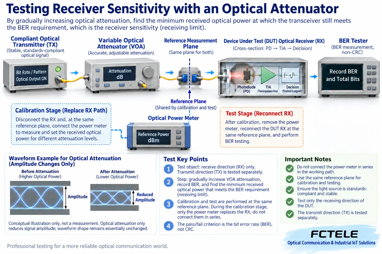
Use a reference plane to fix the measurement location
One unidirectional test setup is a qualified transmitter source, an adjustable optical attenuator, a test patch cord, and the receiver under test. The reference plane at the receiver input is the power location referred to in the report. During calibration, disconnect the receiver under test according to the test plan and connect an optical power meter at that location to measure; then reconnect the receiver under the same connection conditions for the quality test. An ordinary power meter should not be drawn as a transparent inline series device in a continuously operating link.
Some systems use a split monitoring branch or built-in monitoring function. The split ratio and connection losses should be calibrated, and it should be clear how the monitored value is converted to the receive reference plane. Digital diagnostic readings and external meter measurements may have different conditions and cannot be mixed directly without verification. End faces, adapters, wavelength settings, and calibration records all affect the result. After changing patch cords or measurement locations, reconfirm.
Attenuation setting is not the same as receive input power
When calculating receive power, consider transmit power, actual attenuator loss, and other link losses together. dBm represents absolute power, while dB represents loss or ratio; they have different uses. The panel reading of an adjustable device may be extra attenuation or a specified power setting, and there may also be insertion loss; read the instrument mode clearly before testing, and do not mechanically add all numbers directly.
For example, only by subtracting known link loss and attenuator loss from transmit power do you get the estimated receive value under the corresponding conditions. This calculation should be cross-checked with the reference plane measurement, not replace calibration. The two directions of a single-fiber bidirectional device may use different wavelengths, so you need to separately confirm the suitability of the test equipment, the monitoring method, and pairing. You cannot declare the whole link qualified by copying the connection method for one direction of a dual-fiber setup.
Reduce power step by step from a safe baseline
First establish stable communication at a suitable input power, confirm that the tools and baseline are normal, then increase attenuation step by step according to the established test procedure, recording the reference plane power, bit error or frame results, and link status at each step. Near the boundary, use finer steps and check repeatability. The specific step size, duration, and pass conditions should be specified by the corresponding standard and equipment requirements; do not invent thresholds that apply to all interfaces.
Physical bit error testing requires the corresponding pattern, interface, and bit error detection capability, recording errored bits and tested bits. Ethernet whole-device frame testing records transmitted and valid received frames, errors, and discards. The two measure different objects, and you cannot write the packet loss rate of a computer Ping as BER. Link recovery and hysteresis may also affect the location of first pass or fail, so the test direction and reconnection conditions should be stated.
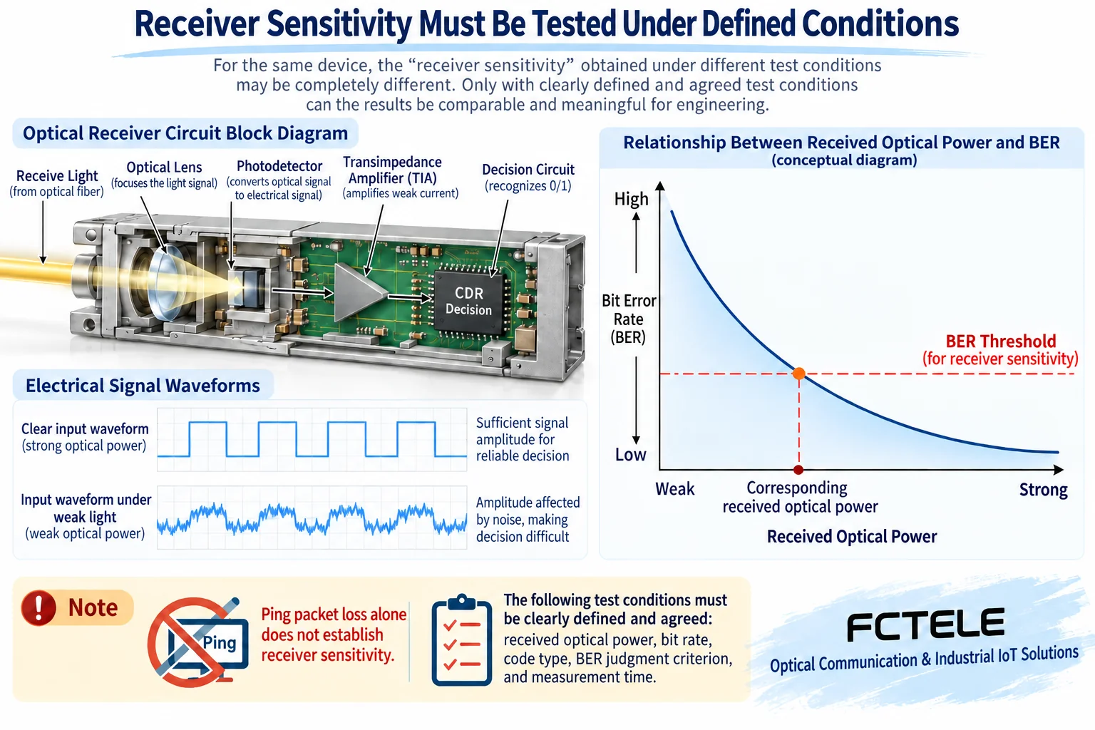
Sensitivity conclusions must include limiting conditions
Keysight optical attenuation test materials explain sensitivity measurement by showing how receive error performance changes with input power; here we refer to the test mechanism, not applying the values of a certain high-speed experimental instrument to 100M or 1G transceivers. Specific specifications may also use different power expressions and stressed signal conditions. The test plan should be confirmed according to the exact optical interface, and cannot simplify all scenarios to a single average power number.
The Feichang Technology B series product page provides fiber, power, and interface options and can serve as an entry point for identifying the device under test. Before testing, request the transmit power, receive range, and applicable conditions of the delivered version; the series maximum distance does not replace sensitivity. If only a field additional attenuation check is done, the conclusion should state the performance of a certain set of equipment, line, and service under specified additional loss, not that a single receiver has passed standard sensitivity certification.
Save boundary results, and also save actual link margin
The report records the transmitter source, device under test, instrument model, calibration, wavelength, reference plane, patch cords, environment, test quality criteria, and raw results for each step. The qualified input range and field margin should be explained separately; short-term connectivity near the boundary does not mean long-term deployment reliability. Both directions should be verified, and when necessary, combined with the connection, temperature changes, and maintenance margin design of the formal optical path.
All attenuation and limit tests are performed in an allowed isolated environment, not randomly approaching disconnection on a production control link. Do not look directly into optical ports or use a flashlight instead of communication detection; clean end faces according to tool specifications, restore the original connections after finishing, and re-accept the actual service. Complete records allow the next maintenance person to reproduce the conditions and also avoid treating a vague packet loss phenomenon as a definite product specification.
Sources: Keysight optical attenuation test mechanism ;Feichang Technology B series details. Related: whole-device testing , optical budget and receive window . The images are generic mechanism illustrations, not actual models, PCBs, measured data, or customer cases; product capabilities are confirmed according to delivery materials.
Translated from the Chinese technical article. Source first published: 2020-03-30. Source last revised: 2026-10-13T11:10:04+08:00. Read the Chinese source
