


8E1 usually means the device can provide the corresponding capacity of eight E1 services. It does not mean eight ordinary Ethernet ports, and it does not guarantee that every product has dual power supplies, a serial port, network management or Ethernet. When reading the parameters, first check the specific model and the ordered configuration, then understand the service capacity, the electrical interfaces, the optical side conditions and the maintenance functions separately.
Eight channels is not one channel at eight times the rate
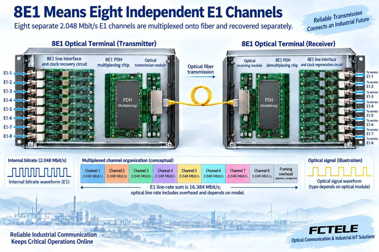
The common nominal line rate for E1 is 2.048 megabits per second. Eight E1 means eight tributaries that can each carry service separately. The transmitting end needs to organize them into a common optical transmission, and the far end restores the corresponding tributaries. Each port does not automatically become a faster E1 just because the other ports are idle. The timeslot, frame and signaling requirements of each service still have to be configured by the service systems at both ends.
Eight times 2.048 gives 16.384 megabits per second, which is only the sum of the nominal line rates of eight E1 channels. The optical side may additionally contain organization, control and coding overhead, so this sum cannot be directly treated as the exact rate of this model’s optical port; the effective application data of eight E1 is also not necessarily equal to this number. Even less can one conclude, merely from the words “eight channels,” that the optical side uses some traditional PDH higher-order group level.
Why per-channel port numbering matters
A multiplexing device has to distinguish where each channel comes from, and the far end then sends it to the corresponding output. During installation, record the channel number, service source, destination and actual usage status. If only six channels are activated, it should be made clear that the other two are reserved, and the unused port status should be handled according to the model’s instructions. An empty port showing a missing input does not necessarily mean the optical section or all six running channels have failed.
Acceptance testing should apply an identifiable test sequence or service to each channel one by one; testing only the first channel is not enough. When channels are cross-connected incorrectly, the optical link and interfaces may still be normal, yet the service has already been delivered to the wrong terminal. For an eight-channel project, correct numbering, cable labels and a handover sheet for both sides say more about whether delivery is complete than a single sentence that “all the lights are on.”
How to choose between 75 and 120 ohms
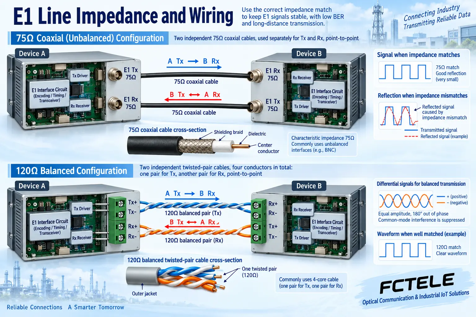
75-ohm unbalanced E1 usually connects transmit and receive separately using coaxial cable; 120-ohm balanced E1 usually uses the corresponding twisted pair. Both methods require matching termination, electrical conditions and device definitions. Changing to a different adapter may only change the mechanical interface and does not complete impedance conversion; you cannot directly connect ports of different impedance with unspecified cable and then just look at whether an electrical signal appears.
DB-type connectors may bring together multiple signals, and RJ45 may also be used for balanced E1, but the pin assignments are not uniformly determined by the shape. You should obtain the pinout diagram, matching breakout device and impedance configuration of the delivered model. The line code is commonly HDB3, and the receiving end also needs to recover a suitable clock. Copper cable length, connectors and reflections can all affect bit errors; a multimeter showing continuity is not enough to prove that a high-speed line is correct.
Read optical parameters together with the actual configuration
Wavelength, fiber type, single or dual fiber, connectors and allowed received power together determine the optical side matching conditions. Dual fiber usually means the local transmit connects to the far end receive; for single fiber, check the complementary wavelength and the matched version. Received power should not only be checked for whether it is above the sensitivity; it must also avoid exceeding the overload condition. Distance is design information that comes with conditions, and actual loss also includes connectors, splices and maintenance margin.
A set of transmit power, sensitivity, DB37 connector and chassis dimensions listed in an old article lacks a corresponding current orderable model, so it should not continue to be used as a uniform specification for all 8E1 devices. When one series on the official website offers multiple optical interface options at the same time, the limit values of the various options also cannot be pieced together into one product. Procurement should obtain the exact ordering number, optical configuration and acceptance conditions, and keep the version documents.
How to distinguish Feichang Technology’s two eight-channel products
The Feichang Technology FCP-E8 official website describes a 19-inch 1U rack-mount unit with one to eight E1 directions, with an optional digital order-wire telephone, and the product description also indicates that Console network management needs to be confirmed according to the configuration. This can serve as a selection clue for an eight-channel leased line. The remote status and loopback capabilities listed on the official website help with maintenance, but from this one cannot infer that it has all the RS232 transparent channels, RS485 cascading or dual power supply hot standby functions mentioned in the old article.
If a project also needs Ethernet, you should look at an integrated model that clearly lists the corresponding interfaces. For example, the public product direction of the FCP-E8G4 is eight E1 plus four gigabit Ethernet ports; the actual service capacity, the working relationship of the ports and the optional configuration need to be confirmed. The two models cannot be regarded as the same product merely because both have eight E1. The nominal rate of each network port, the number of E1 channels and the data the whole unit can carry should be asked about separately; do not claim that all interfaces can be stacked at their maximum rates at will at the same time.
How clock and alarm parameters translate into maintenance
Digital clock recovery helps the device process data according to the input timing, but the whole system still needs a clear clock relationship. The clock choices of the service sides, the transmission equipment and the test set should match each other. Short-term normal operation followed by long-term slips may be related to timing and cannot all be attributed to the fiber. When replacing equipment, save the old settings and check them against the manual within an approved window, to avoid switching master/slave without planning.
Panel alarms have different objects such as the optical section, service input and remote status. If one channel is abnormal, it should be compared with the other channels and with the shared optical section; if all channels are abnormal at the same time, the common conditions should be checked first. The remote power-off and optical path abnormality identification described in Feichang Technology’s product introduction must be tied to the specific model and status table; you cannot assign colors and meanings on your own to unknown indicator names.
A project with six channels in use and two reserved
Suppose there are currently six E1 leased lines and two more will be added in the future. First confirm that the eight-channel configuration meets the actual interface method and that both ends interoperate, then plan the channel table. Establish a baseline on a short link, then connect the formal optical cable, test channel by channel, and then observe all channels in use running together. The example capacity illustrates the method; it is not an actual customer case, and it does not provide recovery time or bit error guarantees for an unknown model.
Finally, deliver the model, impedance, connector and breakout definitions, optical configuration, clock, service ports and test results. If there is an order-wire telephone, network management, Ethernet or backup, accept the corresponding function separately; if it was not ordered, do not write it in the report as already implemented. After the test loopback is completed, it must be exited and the formal application restored. The value of eight-channel parameters is to help establish a verifiable service boundary, not to make the specification list look as long as possible.
Sources: ITU-T G.703 digital interfaces ; Feichang Technology FCP-E8 ; Feichang Technology FCP-E8G4 . The principle illustrations are general principle diagrams; they are general mechanism illustrations, not actual product photos, measured waveforms or certification documents.
Related topics: PDH optical multiplexer and PCM sampling and quantization: at which layer analog voice becomes digital ; How to judge interface compatibility of a PDH optical multiplexer: E1, Ethernet and optical side formats ; How to upgrade an old PDH optical multiplexer network: keep E1, migrate to SDH and packet transport ; How to use PDH optical multiplexer RLB loopback: test path, bit errors and service recovery ; How to select a PDH optical multiplexer: service capacity, optical budget, clock and acceptance ; How to troubleshoot common PDH optical multiplexer faults: continuous alarms, intermittent bit errors and segmented testing
Extended reading on interface adaptation: E1 impedance converter principles, wiring and selection ; E1 impedance mismatch, reflection and bit error acceptance .
Translated from the Chinese technical article. Source first published: 2020-01-18. Source last revised: 2026-10-13T11:10:04+08:00. Read the Chinese source
